|
Sizes, Grades, Bend Radii & Dimensions
| Nominal Hose Bore Size |
Bore Inside Convolutions |
Corroflon Grade (Braid & Cover) |
PTFE Liner Tube Wall Thickness |
O/D of Tube, Braid or Rubber |
Minimum Bend Radius |
* Maximum Continuous Hose Length |
| in |
mm |
in |
mm |
in |
mm |
in |
mm |
in |
mm |
Feet |
Metres |
| 1/2 |
15 |
0.440 |
11.2 |
TO
SS
PB
SS,RC/FP
RC,SI
KYB |
0.05 |
1.4 |
0.63
0.70
0.80
0.90
0.90
0.76 |
16.1
17.8
20.4
22.8
22.8
19.3 |
11/2
11/2
11/2
21/4
21/4
11/2 |
38
38
38
57
57
38 |
100
100
100
100
100
100 |
30
30
30
30
30
30 |
| 3/4 |
20 |
0.620 |
15.7 |
TO
SS
PB
SS,RC/FP
RC,SI
KYB |
0.05 |
1.4 |
0.85
0.91
1.02
1.11
1.11
0.97 |
21.5
23.2
25.8
28.2
28.2
24.7 |
2
2
2
3
3
2 |
51
51
51
76
76
51 |
100
100
100
100
100
100 |
30
30
30
30
30
30 |
| 1 |
25 |
0.847 |
21.5 |
TO
SS
PB
SS,RC/FP
RC,SI
KYB |
0.06 |
1.5 |
1.08
1.14
1.25
1.34
1.34
1.20 |
27.4
29.1
31.7
34.1
34.1
30.6 |
23/4
23/4
23/4
41/4
41/4
23/4 |
70
70
70
105
105
70 |
100
100
100
100
100
100 |
30
30
30
30
30
30 |
| 11/4 |
32 |
1.080 |
27.5 |
TO
SS
PB
SS,RC/FP
RC,SI
KYB |
0.06 |
1.5 |
1.45
1.53
1.72
1.72
1.72
1.57 |
36.8
38.8
43.6
43.8
43.8
40.0 |
31/4
31/4
31/4
43/4
43/4
31/4 |
82
82
82
123
123
82 |
100
100
100
100
100
100 |
30
30
30
30
30
30 |
| 11/2 |
40 |
1.250 |
32.0 |
TO
SS
PB
SS,RC/FP
RC,SI
KYB |
0.06 |
1.5 |
1.65
1.74
1.92
1.93
1.93
1.78 |
42.0
44.1
48.8
49.1
49.1
45.2 |
4
4
4
6
6
4 |
100
100
100
150
150
100 |
100
100
100
100
100
100 |
30
30
30
30
30
30 |
| 2 |
50 |
1.690 |
43.0 |
TO
SS
PB
SS,RC/FP
RC,SI
KYB |
0.07 |
1.8 |
2.11
2.19
2.37
2.38
2.38
2.23 |
53.5
55.6
60.3
60.6
60.6
56.7 |
51/2
51/2
51/2
81/4
81/4
51/2 |
140
140
140
210
210
140 |
100
100
100
100
100
100 |
30
30
30
30
30
30 |
| 21/2 |
65 |
2.120 |
54.0 |
TO
SS
PB
SS,RC/FP
RC,SI
KYB |
0.07 |
1.8 |
2.75
2.83
3.01
3.03
3.03
2.87 |
69.8
71.9
76.6
76.9
76.9
73.0 |
7
7
7
101/2
101/2
7 |
178
178
178
267
267
178 |
65
65
65
65
65
65 |
20
20
20
20
20
20 |
| 3 |
80 |
2.500 |
64.0 |
TO
SS
PB
SS,RC/FP
RC,SI
KYB |
0.07 |
1.8 |
3.27
3.37
3.53
3.57
3.57
3.39 |
83.0
85.7
89.8
90.7
90.7
86.2 |
9
9
9
131/2
131/2
9 |
230
230
230
345
345
230 |
65
65
65
65
65
65 |
20
20
20
20
20
20 |
| 4 |
100 |
3.860 |
98.0 |
TO
SS
PB
SS,RC/FP
RC,SI
KYB |
0.10 |
2.5 |
4.17
4.28
4.44
4.48
4.48
- |
106.0
108.7
112.8
113.7
113.7
- |
113/4
113/4
113/4
173/4
173/4
- |
300
300
300
450
450
- |
32
32
32
32
32
- |
10
10
10
10
10
- |
| 6 |
150 |
5.250 |
130.0 |
TO
SS
PB
SS,RC/FP
RC,SI
KYB |
0.12 |
3.0 |
5.75
5.87
-
6.06
6.06
- |
146.0
149.0
-
154.0
154.0
- |
233/4
233/4
-
351/2
351/2
- |
600
600
-
900
900
- |
28
28
-
28
28
- |
8
8
-
8
8
- |
*Longer lengths may be available to special order if needed
Sizes, Grades, Pressure Ratings, Weights
Corroflon Sizes, Grades, Pressure Ratings & Weights
| Nominal Hose Bore Size |
Bore Inside Convolutions |
Corroflon Grade (Braid & Cover) |
Maximum Working Pressure of Hose |
Burst Pressure |
Weight per Unit Length |
| in |
mm |
in |
mm |
Bar |
psi |
Bar |
psi |
Kg/Mtr |
lb/ft |
| 1/2 |
15 |
0.440 |
11.2 |
TO
SS
PB
SS,RC/FP
RC,SI
KYB |
6
41
31
41
41
15 |
87
595
450
595
595
215 |
24
450
150
450
450
61.5 |
350
6525
2175
6525
6525
890 |
0.21
0.33
0.26
0.49
0.49
0.23 |
0.14
0.22
0.17
0.33
0.33
0.15 |
| 3/4 |
20 |
0.620 |
15.7 |
TO
SS
PB
SS,RC/FP
RC,SI
KYB |
5
35
26
35
35
13 |
70
505
375
505
505
190 |
20
240
105
240
240
52.5 |
290
3480
1520
3480
3480
760 |
0.29
0.45
0.36
0.56
0.56
0.31 |
0.19
0.30
0.24
0.38
0.38
0.21 |
| 1 |
25 |
0.847 |
21.5 |
TO
SS
PB
SS,RC/FP
RC,SI
KYB |
4.5
31
23
31
31
11 |
65
450
334
450
450
160 |
18
200
93
200
200
46.5 |
260
2900
1350
2900
2900
675 |
0.45
0.70
0.56
0.98
0.98
0.49 |
0.30
0.47
0.38
0.66
0.66
0.33 |
| 11/4 |
32 |
1.080 |
27.5 |
TO
SS
PB
SS,RC/FP
RC,SI
KYB |
4
27
20
27
27
10 |
58
390
290
390
390
145 |
16
180
81
180
180
40.5 |
230
2610
1175
2610
2610
585 |
0.53
0.82
0.66
1.12
1.12
0.57 |
0.36
0.55
0.44
0.75
0.75
0.38 |
| 11/2 |
40 |
1.250 |
32.0 |
TO
SS
PB
SS,RC/FP
RC,SI
KYB |
3.5
23
17
23
23
9 |
50
335
245
335
335
130 |
14
120
69
120
120
34.5 |
205
1740
1000
1740
1740
500 |
0.97
1.50
1.20
1.90
1.90
1.05 |
0.65
1.01
0.80
1.27
1.27
0.70 |
| 2 |
50 |
1.690 |
43.0 |
TO
SS
PB
SS,RC/FP
RC,SI
KYB |
3
20
15
20
20
8 |
44
290
215
290
290
115 |
12
100
60
100
100
30 |
175
1450
870
1450
1450
435 |
1.36
2.10
1.68
2.72
2.72
1.47 |
0.91
1.41
1.13
1.82
1.82
0.99 |
| 21/2 |
65 |
2.120 |
54.0 |
TO
SS
PB
SS,RC/FP
RC,SI
KYB |
2.5
16
12
16
16
6 |
36
230
175
230
230
87 |
10
70
48
70
70
24 |
145
1015
695
1015
1015
350 |
1.68
2.58
2.06
3.10
3.10
1.81 |
1.13
1.73
1.38
2.08
2.08
1.21 |
| 3 |
80 |
2.500 |
64.0 |
TO
SS
PB
SS,RC/FP
RC,SI
KYB |
2
14
10
14
14
5 |
29
205
145
205
205
73 |
8
60
42
60
60
21 |
115
870
610
870
870
305 |
2.14
3.29
2.63
3.95
3.95
2.30 |
1.43
2.20
1.76
2.65
2.65
1.54 |
| 4 |
100 |
3.860 |
98.0 |
TO
SS
PB
SS,RC/FP
RC,SI
KYB |
1.5
10
8
10
10
- |
22
145
115
145
145
- |
6
40
30
40
40
-
|
87
580
435
580
580
-
|
3.18
5.05
3.98
6.12
6.14
- |
2.13
3.38
2.67
4.10
4.11
-
|
| 6 |
150 |
5.250 |
130.0 |
TO
SS
PB
SS,RC/FP
RC,SI
KYB |
0.75
5
-
5
5
- |
11
73
-
73
73
-
|
3
20
-
20
20
-
|
44
290
-
290
290
- |
6.50
10.00
-
12.00
12.00
-
|
4.36
6.70
-
8.04
8.04
-
|
EN16643 Hose Assembly Electrical Property Grades
The hose assembly electrical property grades and electrical resistance limits are defined within EN 16643 and tested in accordance with BS EN ISO 8031. Aflex Hose electrically conductive (EC) assemblies are defined in EN 16643 as electrically bonded and given the symbol M. M-grade assemblies exhibit a maximum electrical resistance of 100Ω between end fittings. Aflex Hose anti-static (AS) PTFE liners and rubber covers are termed static dissipative within EN 16643 and given the symbol Ω followed by letters that specify either the liner, cover or both; L=liner, C=cover, CL= cover & liner. Ω-grade covers or liners exhibit an electrical resistance of 103-108Ω.
The table below identifies each EN 16643 electrical grade for a hose assembly along with a brief description and example assembly configuration.
EN16643 Electrical Grade
For Hose Assembly |
EN16643 Description |
Example Hose
Assembly |
| Grade M |
Electrically bonded without static-dissipative lining or cover |
CFLN/GP SS SI
Ends ASA150 Lined
CFLN/GP TO
Ends JIC female |
| M/Ω-L |
Electrically bonded and static-dissipative lining |
CFLN/AS SS SI
Ends ASA150 Lined
CFLN/AS TO
Ends JIC female |
| M/Ω-C |
Electrically bonded and static-dissipative cover |
CFLN/GP SS RC
Ends ASA150 Lined |
| M/Ω-CL |
Electrically bonded and static-dissipative cover and lining |
CFLN/AS SS RC
Ends ASA150 Lined |
| I |
Electrically insulated
(no electrical bonding AND no static-dissipative layers) |
CFLN/GP PB
No helix
Ends ASA150 Lined |
| Ω-L |
Static dissipative lining without electrical bonding |
CFLN/AS TO
Ends ASA150 Lined
CFLN/AS SS
Ends ASA150 PP spigot and flange |
| Ω-C |
Static dissipative cover without electrical bonding |
CFLN/GP SS RC
Ends ASA150 PP spigot and flange |
| Ω-CL |
Static dissipative cover and lining without electrical bonding |
CFLN/AS SS RC
Ends ASA150 PP spigot and flange |
Hose Liners
GP - General Purpose Liner
Purpose
Corroflon GP, SS is the general purpose grade of hose and has been carefully designed to satisfy the widest range of application requirements.
Design & Approvals
The hose liner is manufactured from hose quality grade PTFE conforming to FDA requirements 21 CFR 177.1550 extruded into tube and helically convoluted. It also includes a heavy gauge Grade 304 stainless steel reinforcing wire helically wound into the external root of the convolutions to strengthen the convoluted shape. The braid is high tensile grade 304 stainless steel wire braid to give maximum protection to the hose against internal pressure and external abrasion.
Corroflon GP hose liner tube also conforms to USP Class VI at normal temperatures and at 121˚C (250˚F), see Quality Assurance & Certifications.
AS - Antistatic PTFE Liner
Purpose
Corroflon AS grade is an essential requirement in applications where there is the risk of an electrostatic charge build-up on the inside surface of the PTFE tube which may then discharge through the tube wall. Media passing through which create such a risk are fluids which have a Conductance of less than 10-8 S/m (Siemens per Metre), or 104 pS/m such as fuels, solvents, freons, some WFI (ultra-pure “Water for Injection”) and non-polar organics which are being transferred at a medium to high flow velocity.
All twin or multi phase media, and any non-mixing media, such as powder in air, or water droplets in steam, in gases or in oil, also colloidal fluids constitute a particular hazard for static charge generation, and always require grade AS.
A typical example involves cleaning systems which create a twin phase mixture passing through the hose at high velocity, such as WFI water purged out with air or nitrogen.
If in doubt, consult Aflex Hose.
Design & Approvals
Corroflon AS grade has an anti-static PTFE liner manufactured from FDA 21 CFR 177.1550 approved PTFE, and less than 2.5% of “high purity” Carbon Black material to FDA requirement 21 CFR 178.3297 and European Commission Directive 2007/19/EC. The carbon is encapsulated by the PTFE, and in normal, non-abrasive applications will not come loose to contaminate any fluid passing through. (This has been confirmed by Extractables and Leachables Tests in accordance with BPSA recommendations).
Corroflon AS hose liner tube also conforms to USP Class VI at normal temperatures and at 121˚C (250˚F), see Quality Assurance & Certifications.
Antistatic Hose Assemblies
When “AS” (Antistatic) grade hose is specified, then the hose or hose assembly supplied will be tested in accordance with EN ISO 8031 and meet the Antistatic requirements of EN 16643. This requires, for an antistatic liner or antistatic cover, that the resistance between an appropriately placed foam electrode and a metallic end fitting will be between 103 to 108 ohms per assembly. For hose assemblies which meet these requirements an appropriate Grade “Ω” marking is applied in accordance with EN 16643..
Note: When in service, at least one end fitting must be connected to earth, to permit dissipation of the static charge from the end fitting.
SP - Special Purpose Liner
Purpose
For applications requiring a higher temperature/pressure rating, greater flexibility and improved kink and crush resistance. Also for applications requiring vacuum resistance to -0.9bar for hose sizes larger than 2”.
Design
The convolutions are closer together, yielding greater radial strength to the hose design.
Specifications
As for Corroflon GP, except that the maximum working pressure for wire braided grades is increased by 25%, the weight per metre is increased by 30%, the actual through bore is reduced by 1/8” (3mm), the maximum continuous length is reduced by 50%, the minimum bend radius is reduced by 25% and the angle of cleanability is <80˚.
Available as SP (Natural) and SP, AS (Antistatic) Grades.
Hose Braids
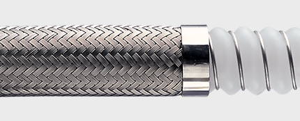
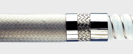
SS - Stainless Steel Braid
Purpose
Stainless Steel braided hose is the general purpose product, and can be used in applications involving high temperatures and working pressures. High tensile AISI 304 stainless steel wire is used, to give maximum pressure resistance and external protection to the hose.
PB - Polypropylene Braid
Purpose
Polypropylene braided hose is often preferred to SS in applications involving frequent handling and movement of the hose, and where temperatures are within the range -30˚C to +100˚C (-22˚F to +212˚F). PB braid is lighter in weight, and any broken strands will not cut the operator’s hands. In addition, PB braid is not prone to “chloride stress corrosion”, and has generally good chemical resistance.
Note: Prolonged exposure to sunlight eventually results in UV degradation of PB braid.
KYB - Kynar Braid (Polyvinylidene Fluoride Monofilament)
Purpose
Kynar Braid is used in the same application as Hastelloy Braid, but only in applications where the reduced pressure ratings of KYB as listed are acceptable. A Safegard Sleeve is always recommended. Monel or Hastelloy wire should be used.
Full details about the applications should be given to Aflex Hose for evaluation and recommendations.
TO - Tube Only (no braid)
Purpose
TO grade hose (available in both GP and AS) is a lightweight hose, used in applications where working pressures are low and where there is no need for the physical protection offered by an external braid.
HB - Hastelloy Braid (C276 grade)
Purpose
Hastelloy Wire Braid is used instead of SS where severe chemical corrosion conditions exist around the outside of the hose. The most usual way in which this can happen is when Chlorine, Bromine, Hydrogen Fluoride, Hydrogen Chloride or Phosgene are being transferred. Diffusion of trace quantities of such fluids or gases through the PTFE liner can lead to atmospherically wetted halogen chemicals attacking the braid material, in which case the Hastelloy Braid would be resistant up to 60˚C (140˚F) maximum. This should only be used, however, in conjunction with a Monel or Hastelloy Helix Wire.
Full details about the applications should be given to Aflex Hose for evaluation and recommendations.
Specifications
Same as for SS in Specifications & Properties, except the Burst Pressures and the Maximum Working Pressures are both reduced to 80% of the SS pressures listed.
Also, the sizes range is restricted, from 1/2”up to 2” bore only.
SPECIAL NOTE:
EC - Electrical Continuity (Also known as “Electrically Bonded”)
The requirements for this are specified in the German Document BRG 132 and EN 16643, when tested in accordance with EN ISO 8031, which requires that the resistance between end fittings shall be <102 ohms per assembly. For hose assemblies which meet this requirement a Grade “M” marking can be applied in accordance with EN 16643.
Hose Rubber Covers
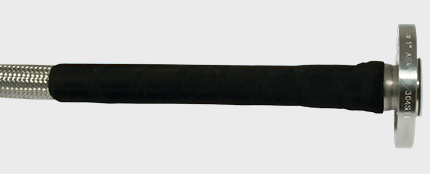
RC - EPDM Rubber Covered - Antistatic and Fire Proof Black Rubber Cover
Purpose
For the most rugged applications where the hose may be subjected to rough treatment and severe external abrasion. Also for hygienic applications, where the external cleanability of the hose is of prime importance and in applications where the hose is required to be Fire Proof, or to have an Antistatic cover.
Design
An SS braided hose has a black, antistatic EPDM external rubber cover extruded directly onto the braid to produce a super-smooth external surface finish. Sizes above 2” bore are hand-wrapped, not extruded.
EPDM has excellent chemical resistance, and the hose has a temperature range from -40˚C, -40˚F up to +150˚C, +302˚F.
Fire Proof
As well as providing an Antistatic cover, Corroflon RC hose is also Fire Proof in accordance with Specification BS5173 Section 103.13 part 6.2 (Fireproof). This specification calls for an 1100˚C (2012˚F) flame to be applied to the hose at minimum bend radius, maximum operating pressure (water), and one end fitting under vibration. The hose must withstand at least 15 minutes without leakage.
Hose assemblies are Fire Resistant, but can be rendered Fire Proof by the addition of DRC-300 at both ends - see below.
Corroflon RC hose meets the requirements of German Safety Regulation TRBF 131/2 and EN 16643 flame resistance.
Antistatic
Corroflon RC hose is antistatic (AS) in accordance with EN 16643 limits and tested in accordance with EN ISO 8031.
SI - Silicone Rubber Cover
Purpose
As for RC hose, but where the hose may be required to withstand temperatures from -73˚C, -100˚F up to +224˚C, +435˚F. SI grade hose is semi-transparent, allowing visual monitoring of the braid.
Design
An SS braided hose assembly has an external smooth finish, platinum cured silicone rubber cover extruded (>50 metres) or hand-wrapped (<50 metres), and vulcanised directly onto the braid.
Specifications
The Silicone rubber cover has been tested and conforms to the requirements of USP Class VI, see Quality Assurance & Certifications.
RC-300 - Rubber Covered 300mm at End
Purpose
In applications where excessive flexing of the hose at the end fitting occurs, it is sometimes necessary to ‘stiffen’ the hose in this area, to prevent kinking.
Design
A layer of rubber is hand-wrapped and vulcanised directly to the ferrule, and 300mm (12 inch) along the hose from the fitting. This can be done either on an SS braided hose (RC-300 or SI-300) or on a rubber covered hose as a 300mm (12 inch) long double layer of rubber at the end (DRC-300 or DSI-300).
Hose External Protections
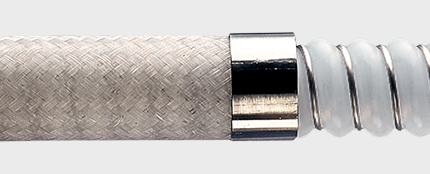
SG - Safegard Protection Sleeve
Purpose
To protect the hose against external abrasion and mechanical damage. For use in applications where maximum external protection is required with minimum extra hose weight. Particularly useful with PB or KYB hose, where a rubber cover is not an option.
Design
A lightweight black, HDPE (High Density Poly Ethylene) strip spirally wound around the outside of the hose over its whole length, secured to each end fitting by crimping under a SS ferrule.
Limitations
Safegard is applicable to all hose types and all hose sizes from 1/2” up to 4”.
Safegard is limited to use within a temperature range from -40˚C (-40˚F) up to +110°C (230°F). Internal fluid temperatures up to 140°C (284°F) are acceptable, when external temperatures are ambient.
The minimum hose assembly length must be doubled, if Safegard is being used and the maximum assembly lengths for all sizes are capped at 20 metres (65 feet).
The other hose usage limitation specifications are not altered by the addition of Safegard.
Safegard is available with anti-static properties and complies with the requirements of a static-dissipative cover within EN 16643. Request details upon enquiry.
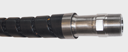
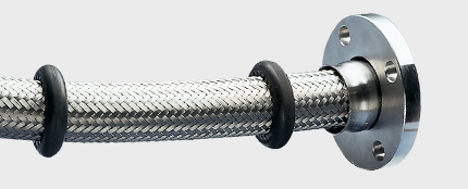
SR - Scuff Rings
Purpose
For medium duty applications where the hose requires some protection against abrasion when dragged over the ground, but where a full rubber cover would be too heavy and cumbersome. Also for PB and KYB braided hose, which cannot be Rubber Covered.
Design
Specially moulded abrasion resistant rubber scuff rings are placed every half metre along the hose.
Limitations
Available for hose sizes 1” (25mm) to 2” (50mm) only. The operating temperature should not exceed 140˚C (284˚F) (internal).
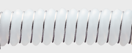
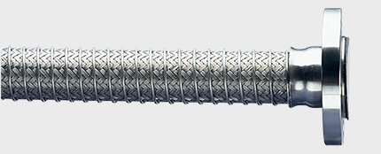
PC - Protection Coil
Purpose
For applications where the hose requires protection against abrasion when dragged over the ground, but where any rubber reinforcement is not permissible due to temperature, chemicals etc.
Design
A stainless steel wire helix is wound onto the braid and welded to the ferrules at each end.
Limitations
Available for all sizes and grades of hose, including rubber covered.
The maximum assembly lengths for all sizes are capped at 20 metres (65 feet).
Specifications
As for the relevant hose grade.
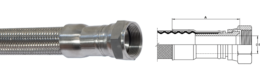
Non-lined Fittings
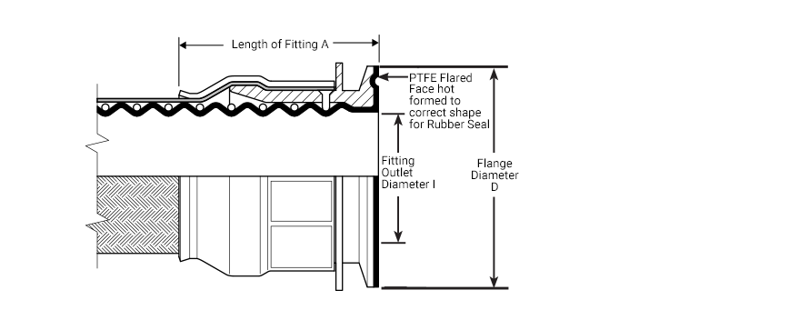
Flange Specification
- ANSI B16.5 (also ASME B16.5) Class 150# and 300#
- *DIN PN10/16/40 up to 2” size, PN10/16 from 21/2 ” up to 6” size
- JIS 10K
- Other Pressure Ratings and Flange Specifications are also available
*The dimensions for flanges to the different pressure ratings are identical, so they are inter-changeable.
Maximum Pressure Ratings for Flange Fittings
- ANSI 150# = 16 Bar (230 psi), ANSI 300# = 32 Bar (460 psi)
- DIN PN10 = 10 Bar (145 psi), DIN PN16 = 16 Bar (230 psi), DIN PN40 = 40 Bar (580psi)
End Fitting Materials
- Flanges in Grade 304 SS
- Flange Retainers in Grade 316L SS
- Ferrules, most in Grade 304 SS, some sizes in Grade 316 SS
Alternative Options for Flange Component only:
- Zinc Plated Carbon Steel
- Grade 316 Stainless Steel
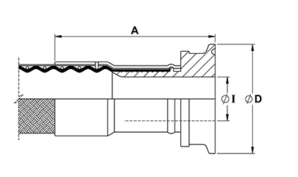
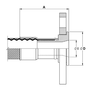 The above drawing relates to sizes 1", 11/2 ", 2"
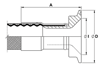
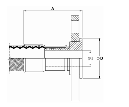 The above drawing relates to all other sizes
| Nominal Hose Size |
*Fitting Length A
PN |
Flared Diameter D
PN/10/16 |
Fitting Inside Diameter I |
Weight of Fitting |
| in |
mm |
in |
mm |
in |
mm |
in |
mm |
Kg |
Lbs |
| 1/2 |
13 |
2.20 |
56 |
1.77 |
45 |
0.39 |
10 |
0.76 |
1.69 |
| 3/4 |
20 |
3.11 |
79 |
2.28 |
58 |
0.63 |
16 |
1.06 |
2.35 |
| 1 |
25 |
3.46 |
88 |
2.68 |
68 |
1.12 |
28.5 |
1.36 |
3.00 |
| 1 1/4 |
32 |
3.98 |
101 |
3.07 |
78 |
1.02 |
26 |
1.72 |
3.79 |
| 1 1/2 |
40 |
4.69 |
119 |
3.46 |
88 |
1.69 |
43.10 |
2.49 |
5.50 |
| 2 |
50 |
4.69 |
119 |
4.02 |
102 |
2.15 |
54.5 |
3.57 |
7.87 |
| 2 1/2 |
65 |
5.20 |
132 |
4.80 |
122 |
2.24 |
57 |
4.20 |
9.26 |
| 3 |
80 |
5.28 |
134 |
5.43 |
138 |
2.64 |
67 |
5.68 |
12.52 |
| 4 |
100 |
5.51 |
140 |
6.22 |
158 |
3.50 |
89 |
8.42 |
18.56 |
| 6 |
150 |
7.00 |
178 |
8.35 |
212 |
5.51 |
140 |
12.30 |
27.12 |
*Fitting Lengths listed are for Corroflon braided only hose grades (SS, PB, HB, KYB). Approximately 33% longer lengths apply to the rubber covered hose grades (RC, SI, FP)
| Nominal Hose Size |
*Fitting Length A
ASA |
Flared Diameter D
ASA150 |
Fitting Inside Diameter I |
Weight of Fitting |
| in |
mm |
in |
mm |
in |
mm |
in |
mm |
Kg |
Lbs |
| 1/2 |
13 |
2.13 |
54 |
1.37 |
34.9 |
0.39 |
10 |
0.76 |
1.69 |
| 3/4 |
20 |
2.99 |
76 |
1.69 |
42.9 |
0.63 |
16 |
1.06 |
2.35 |
| 1 |
25 |
2.95 |
75 |
2.00 |
50.8 |
0.79 |
20.24 |
1.36 |
3.00 |
| 1 1/4 |
32 |
3.78 |
96 |
2.50 |
63.5 |
1.02 |
26 |
1.72 |
3.79 |
| 1 1/2 |
40 |
4.25 |
108 |
2.87 |
73.0 |
1.25 |
31.75 |
2.49 |
5.50 |
| 2 |
50 |
4.41 |
112 |
3.63 |
92.1 |
1.75 |
44.45 |
3.57 |
7.87 |
| 2 1/2 |
65 |
5.27 |
134 |
4.12 |
104.5 |
2.24 |
57 |
4.20 |
9.26 |
| 3 |
80 |
5.43 |
138 |
5.00 |
127.0 |
2.64 |
67 |
5.68 |
12.52 |
| 4 |
100 |
5.51 |
140 |
6.19 |
157.2 |
3.50 |
89 |
8.42 |
18.56 |
| 6 |
150 |
7.00 |
178 |
8.50 |
215.9 |
5.51 |
140 |
12.30 |
27.12 |
PTFE lined Fittings
Flange Specification
- ANSI B16.5 (also ASME B16.5) Class 150# and 300#
- *DIN PN10/16/40 up to 2” size, PN10/16 from 21/2 ” up to 6” size
- JIS 10K
- Other Pressure Ratings and Flange Specifications are also available
*The dimensions for flanges to the different pressure ratings are identified, so they are inter-changeable.
Maximum Pressure Ratings for Flange Fittings
- ANSI 150# = 16 Bar (230 psi), ANSI 300# = 32 Bar (460 psi)
- DIN PN10 = 10 Bar (145 psi)
- DIN PN16 = 16 Bar (230 psi), DIN PN40 = 40 Bar (580psi)
End Fitting Materials
- Flanges in Grade 304 SS
- Flange Retainers in Grade 316L SS
- Ferrules, most in Grade 304 SS, some sizes in Grade 316L SS
Alternative options for Flange component only:
- Zinc Plated Carbon Steel
- Grade 316 Stainless Steel
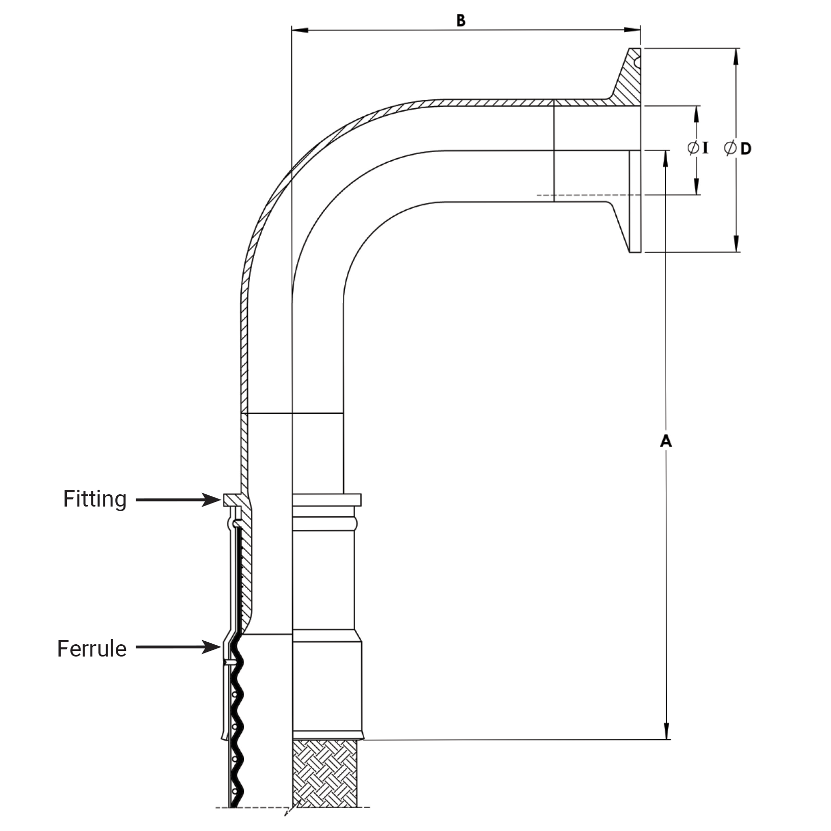
90˚ Elbow Flange Fittings
90˚ Elbow Integral PTFE lined Flange Fittings are available for 1”, 11/2” & 2”.
Nominal Size -
Flange & Hose |
*Fitting Length A
ASA |
*Fitting Length A
PN |
Flared Diameter D |
Recommended Bolt
Tightening Torques |
Weight of Fitting |
| in |
mm |
in |
mm |
in |
mm |
ASA 150
mm |
PN/10/16
mm |
ft.lbs |
Nm |
Kg |
Lbs |
| 1/2 |
15 |
2.09 |
53 |
2.09 |
53 |
32.0 |
32.0 |
8 |
10.79 |
0.54 |
1.19 |
| 3/4 |
20 |
2.28 |
58 |
2.34 |
59.5 |
43.0 |
50.0 |
8 |
10.79 |
0.88 |
1.94 |
| 1 |
25 |
2.28 |
58 |
2.36 |
60 |
50.8 |
63.5 |
10 |
13.73 |
0.96 |
2.11 |
| 11/4 |
32 |
2.48 |
63 |
2.52 |
64 |
63.0 |
78.0 |
12 |
16.67 |
1.36 |
2.99 |
| 11/2 |
40 |
2.40 |
61 |
2.50 |
63.5 |
73.0 |
88.0 |
15 |
20.59 |
1.75 |
3.85 |
| 2 |
50 |
2.52 |
64 |
2.62 |
66.5 |
92.0 |
102.0 |
25 |
34.32 |
2.70 |
5.94 |
| 21/2 |
65 |
3.11 |
79 |
3.19 |
81 |
105.0 |
122.0 |
30 |
41.18 |
4.00 |
8.80 |
| 3 |
80 |
3.11 |
79 |
3.11 |
79 |
127.0 |
127.0 |
40 |
53.94 |
5.00 |
11.00 |
| 4 |
100 |
5.20 |
132 |
5.20 |
132 |
158.0 |
158.0 |
40 |
53.94 |
7.00 |
15.40 |
| 6 |
150 |
3.66 |
93 |
3.66 |
93 |
213.0 |
213.0 |
50 |
67.67 |
13.00 |
29.00 |
*Fitting Lengths listed are for Corroflon braided only hose grades (SS, PB, HB, KYB). Approximately 33% longer lengths apply to the rubber covered hose grades (RC, SI, FP).
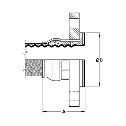
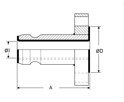
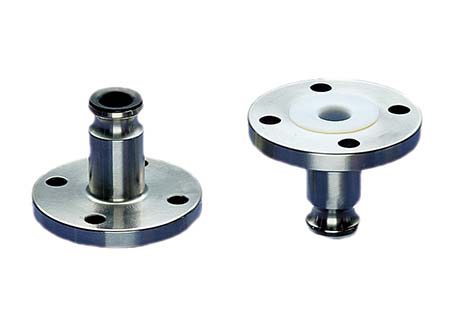
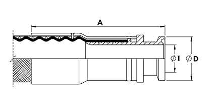
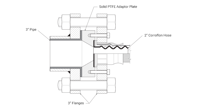
‘Step-Up’ PTFE Lined Flange Fitting Design for Corroflon Hose
Adapting for Different Flange Sizes
To fit larger than nominal flange sizes
It may be necessary to fit a larger than nominal flange size to the hose - for example, 3” flange fitted to one end of a 2” hose - in which case it may also be necessary to increase the diameter of the sealing face to the correct size for the larger flange. This can be achieved by means of a flange adaptor as shown.
To fit smaller than nominal flange sizes
Within limits, it is also possible to make up an assembly with a flange one size smaller than the nominal size. The smaller flange is bored out and fitted to the larger hose and, if necessary, the flared diameter is reduced to suit.
Consult the supplier if a different flange size is required.
Female Fittings
End Fitting Specification
- Generally in accordance with A-A-59326 (replaces MIL-C-27487) and EN14420-1 (replaces DIN 2828), and all are fully interchangeable.
Temperature and Pressure Ratings
- When used with a Buna N Gasket all sizes up to 16 Bar (230 psi) and up to a maximum temperature of 65˚C (149˚F).
- When used with FEP, Fluoro Rubber or other encapsulated gaskets all sizes up to 10 Bar (145 psi) and up to a maximum temperature of 204˚C (400˚F).
End Fitting Materials
- Spigot in Grade 316L SS
- Body in Grade 316C SS
- Ferrules, most in Grade 304 SS, some sizes in Grade 316L SS
- Standard Gasket is Buna N (Nitrile) Rubber.
- FEP encapsulated Silicone Rubber Gaskets also available.
90˚Elbow Cam & Groove Fittings (Lined Only)
- 90˚ Elbow Integral PTFE lined Cam & Groove Fittings are available for sizes 1”, 11/2 ” and 2”.
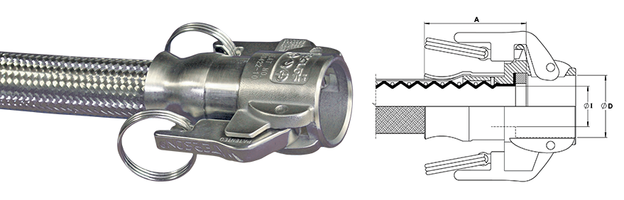
Swivelling, Locking Arm Female Cam and Groove Fittings - Non Lined
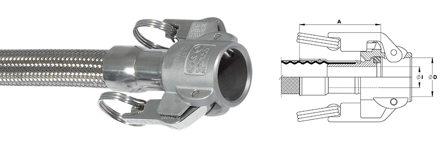
| Nominal Hose Size |
*Fitting Length A |
Cam Sleeve Inside Diameter D |
Fitting Inside Diameter I |
Weight of Fitting |
| in |
mm |
in |
mm |
in |
mm |
in |
mm |
Kg |
Lbs |
| 3/4 |
20 |
3.11 |
79 |
1.26 |
32 |
0.63 |
15.9 |
0.40 |
0.88 |
| 1 |
25 |
3.07 |
78 |
1.46 |
37 |
0.75 |
19.1 |
0.51 |
1.12 |
| 11/2 |
40 |
4.13 |
105 |
2.13 |
54 |
1.25 |
31.8 |
0.88 |
1.94 |
| 2 |
50 |
4.25 |
108 |
2.52 |
64 |
1.75 |
44.5 |
1.15 |
2.53 |
| 21/2 |
65 |
4.49 |
114 |
3.03 |
77 |
2.25 |
57.2 |
1.41 |
3.10 |
| 3 |
80 |
4.61 |
117 |
3.62 |
92 |
2.63 |
66.7 |
1.89 |
4.17 |
*Fitting Lengths listed are for Corroflon braided only hose grades (SS, PB, HB, KYB). Approximately 33% longer lengths apply to the rubber covered hose grades (RC, SI, FP).
Fixed, Locking Arm Female Cam and Groove Fitting - Integral PTFE Lined
| Nominal Hose Size |
*Fitting Length A |
Cam Sleeve Inside Diameter D |
Fitting Inside Diameter I |
Weight of Fitting |
| in |
mm |
in |
mm |
in |
mm |
in |
mm |
Kg |
Lbs |
| 3/4 |
20 |
2.48 |
63 |
1.26 |
32 |
0.70 |
17.8 |
0.39 |
0.86 |
| 1 |
25 |
2.40 |
61 |
1.46 |
37 |
0.95 |
24.1 |
0.50 |
1.10 |
| 11/2 |
40 |
2.56 |
65 |
2.13 |
54 |
1.44 |
36.7 |
0.86 |
1.89 |
| 2 |
50 |
2.56 |
65 |
2.52 |
64 |
1.94 |
49.3 |
1.10 |
2.42 |
*Fitting Lengths listed are for Corroflon braided only hose grades (SS, PB, HB, KYB). Approximately 33% longer lengths apply to the rubber covered hose grades (RC, SI, FP).
Notes: For Integral PTFE Lined Fittings Only
FEP Gaskets require higher clamping forces to flatten the Seal and make the joint. This is made easier by ‘pre-setting’ these gaskets by clamping Polypropylene Cam Male Inserts to the assembled fittings, which must then be kept in place during storage, until use.
Any Customer’s Own ‘Special’ Gaskets must be pre-supplied to Aflex for special assembly and testing of hose assemblies, to ensure suitability.
Male Fittings
End Fitting Specification
- Generally in accordance with A-A-59326 (replaces MIL-C-27487) and EN14420-1 (replaces DIN 2828), and all are fully interchangeable.
Temperature and Pressure Ratings
- Temperature and pressure determined by the type of gasket in the Female connecting component.
End Fitting Materials
- Fittings in Grade 316L SS
- Ferrules, most in Grade 304 SS, some sizes in Grade 316L SS
- Adaptor Flange Only in Grade 304 SS
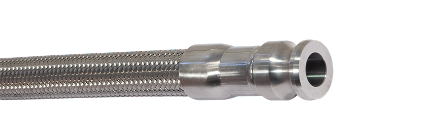
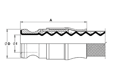 Integral PTFE Lined Cam & Groove Male Fitting
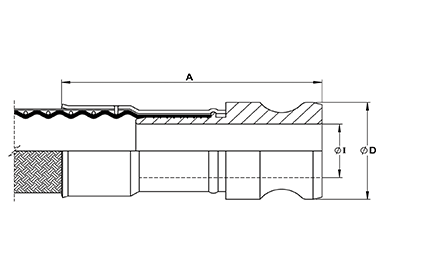 Non-Lined Cam & Groove Male Fitting
| Nominal Hose Size |
øD |
Fitting Length A |
Non-Lined Inside
Diameter I |
Lined Inside
Diameter B |
Weight of Fitting |
| in |
mm |
in |
mm |
in |
mm |
in |
mm |
in |
mm |
Kg |
Lbs |
| 3/4 |
20 |
1.26 |
32 |
3.38 |
86 |
0.63 |
15.88 |
0.70 |
17.78 |
0.40 |
0.88 |
| 1 |
25 |
1.46 |
37 |
3.66 |
93 |
0.80 |
20.24 |
0.88 |
22.35 |
0.49 |
1.08 |
| 11/2 |
40 |
2.13 |
54.0 |
5.00 |
127 |
1.25 |
31.75 |
1.12 |
28.50 |
0.81 |
1.78 |
| 2 |
50 |
2.52 |
64 |
5.67 |
144 |
1.75 |
44.45 |
1.77 |
44.96 |
1.05 |
2.31 |
*Fitting Lengths listed are for Corroflon braided only hose grades (SS, PB, HB, KYB). Approximately 33% longer lengths apply to the rubber covered hose grades (RC, SI, FP).
PTFE Lined Male Cam and Groove X Flange Adaptors
Cam Action
Adaptor Size |
Flange Size &
Specification |
øD |
A |
I |
Weight of Fitting |
| in |
mm |
in |
mm |
in |
mm |
in |
mm |
Kg |
Lbs |
| 1 |
25 |
1"ANSI/1507 |
2.00 |
50 |
4 1/8 |
105 |
0.84 |
21 |
1.246 |
2.75 |
| 1 |
25 |
DN25/PN16 |
2.58 |
64 |
4 1/8 |
105 |
0.84 |
21 |
1.538 |
3.39 |
| 1 1/2 |
40 |
11/2"ANSI/1507 |
2.87 |
73 |
4 3/8 |
118 |
1.35 |
34 |
2.228 |
4.92 |
| 1 1/2 |
40 |
DN40/PN16 |
3.47 |
88 |
4 3/4 |
118 |
1.35 |
34 |
2.753 |
6.07 |
| 2 |
50 |
2" ANSI/1507 |
3.63 |
92 |
4 3/4 |
118 |
1.69 |
43 |
3.359 |
7.40 |
| 2 |
50 |
DN50/PN16 |
4.02 |
102 |
4 3/4 |
118 |
1.69 |
43 |
3.714 |
8.19 |
Note: Other Flange Specifications and Pressure Ratings are also available. Non-Lined adaptors and Female Cam and Groove X Flange Adaptors are also available, to special order.
PTFE lined & flared Fittings
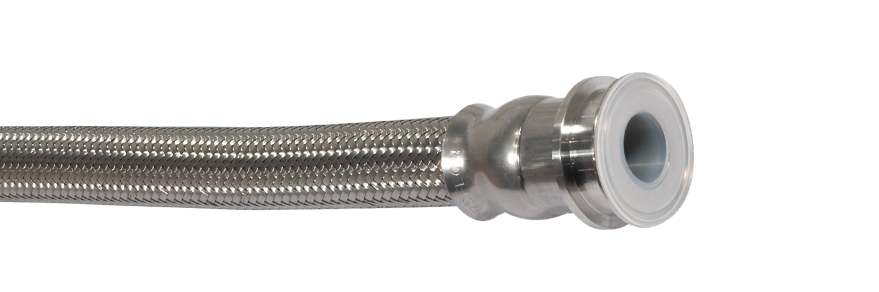
End Fitting Specification
- BS4825 Pt 3 (UK)
- ASME BPE-a-2007 (USA)
- DIN32676 (Europe, DN Sizes)
- ISO 1127 (Europe) (Non Standard, Specials Only)
Temperature and Pressure Ratings
- Pressures up to 16 Bar (230 psi)
- Temperatures up to 180˚C (356˚F)
- Higher Pressures & Temperatures possible with Special Clamps and appropriate Seals.
End Fitting Materials
- Fittings in Grade 316L SS (= BS 316 S11 = EN 1.4404)
- Ferrules, most in Grade 304 SS, some sizes in Grade 316L SS
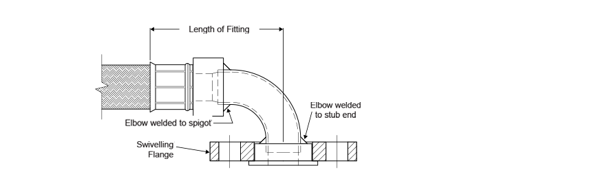
90˚ Elbows
PTFE Lined 90˚ elbow fittings are available for some sizes and grades
| Nominal Hose Size |
Nominal Pipe Size |
Outlet Diameter I |
Flange Diameter D |
*Length of Fitting A |
Weight of Fitting |
| in |
mm |
in |
mm |
in |
mm |
in |
mm |
in |
mm |
Kg |
Lbs |
| 1/2 |
15 |
1/2 |
12.7 |
3/8 |
9.5 |
0.984 |
25.0 |
1.96 |
50 |
0.075 |
0.17 |
| 1 |
25 |
1 |
25.4 |
7/8 |
22.2 |
1.984 |
50.5 |
2.36 |
60 |
0.226 |
0.50 |
| 1 1/2 |
40 |
11/2 |
38.1 |
13/8 |
34.9 |
1.984 |
50.5 |
2.48 |
63 |
0.269 |
0.59 |
| 2 |
50 |
2 |
50.8 |
17/8 |
47.6 |
2.516 |
64.0 |
2.60 |
66 |
0.407 |
0.90 |
| 2 1/2 |
65 |
21/2 |
63.4 |
23/8 |
60.3 |
3.050 |
77.5 |
3.22 |
82 |
0.510 |
1.12 |
| 3 |
80 |
3 |
76.1 |
27/8 |
73.0 |
3.580 |
91.0 |
3.22 |
82 |
0.593 |
1.30 |
*Fitting Lengths listed are for Corroflon braided only hose grades (SS, PB, HB, KYB). Approximately 33% longer lengths apply to the rubber covered hose grades (RC, SI, FP).
Non-lined Fittings
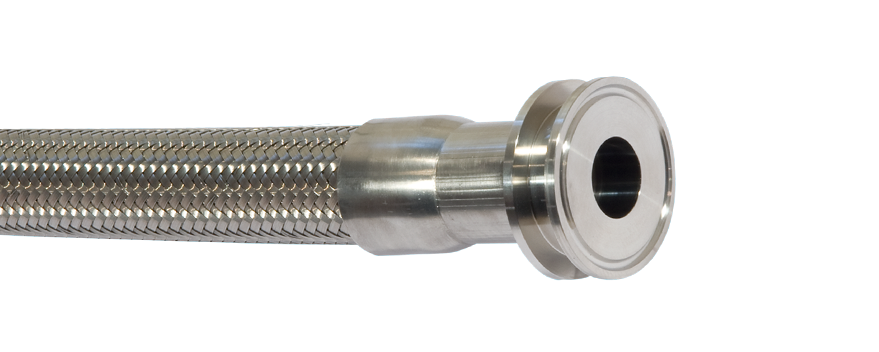
End Fitting Specification
- BS4825 Pt 3 (UK)
- ASME BPE-a-2007 (USA)
- DIN32676 (Europe, DN Sizes)
- ISO 1127 (Europe) (Non Standard, Specials Only)
Temperature and Pressure Ratings
For Standard Clamp and Standard (EPDM) Gasket
- Pressures up to 16 Bar (230 psi)
- Temperatures up to 120˚C (250˚F)
- Higher Pressures and Temperatures with Special Clamps and Gaskets
End Fitting Materials
- Fittings in AISI 316L = EN 1.4404 = BS 316 S11. Internal Bores all Electropolished to <15µin Ra (<0.375µ mtr).
- Ferrules, most in Grade 304 SS, some sizes in Grade 316L SS
Outlet Diameters (Inch pipe sizes only)
The outlet diameters as listed are in accordance with BS4825. The ASME specification, however, requires these diameters to be 0.005” (0.125mm) less in each case. An Outlet Diameter tolerance of +0.000 -0.005” has therefore been applied, so that the same fitting satisfies requirements of both specifications.
Mini-sanitary Triclamp (triclover) Fittings
| Nominal Hose Size |
Nominal Pipe Size |
*Fitting Length A |
Flange Dia. D |
Outlet Dia. I |
Weight of Fitting |
| in |
mm |
in |
mm |
in |
mm |
Kg |
Lbs |
| 1/2" |
1/2" & DN10 |
2.13 |
54 |
0.984 |
25.0 |
3/8 |
9.5 |
0.05 |
0.11 |
| 1/2" |
3/4" |
2.13 |
54 |
0.984 |
25.0 |
5/8 |
16.0 |
0.04 |
0.09 |
| 3/4" |
3/4" |
3.03 |
77 |
0.984 |
25.0 |
5/8 |
16.0 |
0.05 |
0.11 |
Sanitary Triclamp (triclover) Fitting
| Nominal Hose Size |
Nominal Pipe Size |
*Fitting Length A |
Flange Dia. D |
Outlet Dia. I |
Weight of Fitting |
| in |
mm |
in |
mm |
in |
mm |
Kg |
Lbs |
| 1/2" |
1" |
2.01 |
51 |
1.984 |
50.5 |
7/8 |
22.2 |
0.13 |
0.28 |
| 3/4" |
DN15 |
2.96 |
75 |
1.156 |
34.0 |
5/8 |
16.0 |
0.12 |
0.26 |
| 3/4" |
ISO (DN) 15 |
2.96 |
75 |
1.984 |
50.5 |
0.713 |
18.10 |
0.16 |
0.35 |
| 3/4" |
ISO (DN) 20 |
2.96 |
75 |
1.984 |
50.5 |
0.934 |
23.7 |
0.15 |
0.33 |
| 1" |
1" |
3.39 |
86 |
1.984 |
50.5 |
7/8 |
22.2 |
0.25 |
0.54 |
| 1" |
DN25 |
3.39 |
86 |
1.984 |
50.5 |
1 |
26.0 |
0.24 |
0.52 |
| 1" |
ISO (DN) 25 |
3.39 |
86 |
1.984 |
50.5 |
1.170 |
29.7 |
0.23 |
0.52 |
| 1" |
1 1/2" |
3.39 |
86 |
1.984 |
50.5 |
1 3/8" |
34.9 |
0.22 |
0.48 |
| 1 1/2" |
1 1/2" |
4.02 |
102 |
1.984 |
50.5 |
1 3/8" |
34.9 |
0.27 |
0.59 |
| 1 1/2" |
DN40 |
4.02 |
102 |
1.984 |
50.5 |
1 1/2" |
38.0 |
0.25 |
0.56 |
| 2" |
2" |
4.02 |
108 |
2.516 |
64.0 |
1 7/8" |
47.6 |
0.39 |
0.86 |
| 2" |
DN50" |
4.25 |
108 |
2.516 |
64.0 |
1.975 |
50.0 |
0.37 |
0.82 |
| 2" |
2 1/2" |
4.13 |
105 |
3.047 |
77.5 |
2 3/8" |
60.3 |
0.42 |
0.92 |
| 2" |
DN65 |
4.13 |
105 |
3.047 |
77.5 |
2.600 |
66.0 |
0.40 |
0.88 |
| 2" |
3" |
4.53 |
115 |
3.579 |
91.0 |
2 7/8" |
73.0 |
0.68 |
1.50 |
| 2" |
DN80 |
4.53 |
115 |
4.176 |
106.0 |
3.191 |
81.0 |
1.12 |
2.47 |
*Fitting Lengths listed are for Corroflon braided only hose grades (SS, PB, HB, KYB). Approximately 33% longer lengths apply to the rubber covered hose grades (RC, SI, FP).
90° Elbow Fitting
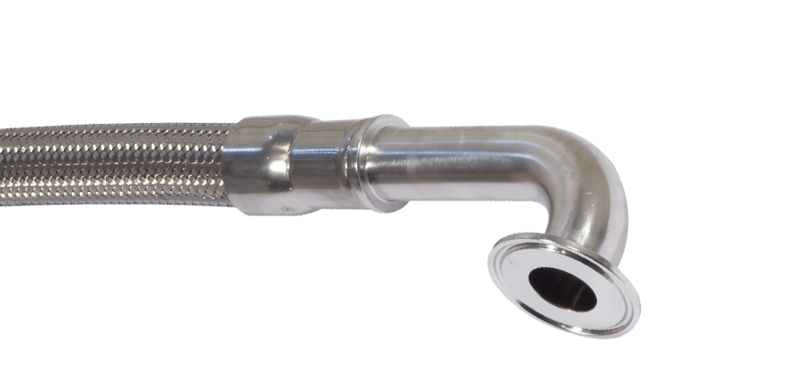
End Fitting Specification
- BS4825 Pt 3
- ASME-BPE-a
- Others to Special Order
Temperature and Pressure Ratings
For Standard Clamp and Standard (EPDM) Gasket
- Pressures up to 16 Bar (230 psi)
- Temperatures up to 120˚C (250˚F)
- Higher Pressures and Temperatures with Special Clamps and Gaskets.
End Fitting Materials
- Fittings in Grade AISI 316L = EN 1.4404 = BS 316 S11
- Internal Bore average 15µin Ra, Electropolished if required
- Ferrules, most in Grade 304 SS, some sizes in Grade 316L SS
Outlet Diameters
The outlet diameters as listed are in accordance with BS4825. The ASME specification, however, requires these diameters to be 0.005” (0.125mm) less in each case. An Outlet Diameter tolerance of +0.000 -0.005” has therefore been applied, so that the same fitting satisfies requirements of both specifications.
| Nominal Hose Size |
*Centre Line To Fitting End A |
Centre Line to Face B |
Flange Diameter D |
*Outlet Diameter I |
Weight of Fitting |
| in |
mm |
in |
mm |
mm |
mm |
in |
mm |
in |
mm |
Kg |
Lbs |
| 1/2 |
13 |
5.78 |
147 |
1.60 |
41.0 |
0.984 |
25.0 |
3/8 |
9.5 |
0.137 |
0.30 |
| 3/4 |
20 |
6.41 |
163 |
1.60 |
41.0 |
0.984 |
25.0 |
5/8 |
16.0 |
0.205 |
0.45 |
| 1 |
25 |
6.53 |
166 |
2.00 |
51.0 |
1.984 |
50.5 |
7/8 |
22.2 |
0.347 |
0.77 |
| 11/2 |
40 |
7.99 |
203 |
2.75 |
70.0 |
1.984 |
50.5 |
13/8 |
34.9 |
0.590 |
1.30 |
| 2 |
50 |
9.33 |
237 |
3.50 |
88.9 |
2.519 |
64.0 |
17/8 |
47.6 |
0.928 |
2.05 |
*Fitting Lengths listed are for Corroflon braided only hose grades (SS, PB, HB, KYB). Approximately 33% longer lengths apply to the rubber covered hose grades (RC, SI, FP).
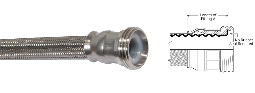
DIN 11851 Fittings
Description
- DIN 11851 male and female fittings, integrally PTFE lined.
- Also available non-lined, up to 4” (100mm), to special order.
Specification
- Generally to German DIN 11851 specification.
Note: The PTFE lined male fitting is designed to be used without a rubber seal. Please note that when connecting to a PTFE Lined DIN11851 Male, extra spanner tightening of the nut is sometimes required in order to provide a leak free connection.
End Fitting Materials
- Spigots in Grade 316L SS
- Nuts in Grade 304 SS
- Ferrules, most in Grade 304 SS, some sizes in Grade 316L SS
Temperature & Pressure Ratings
- Sizes up to 11/2” MWP = 40 Bar (580 psi) up to 140˚C (284˚F)
- Sizes 2” to 3” MWP = 25 Bar (360 psi) up to 140˚C (284˚F)
Except where the applicable hose pressure/temperature ratings are lower.
90˚ Elbows
PTFE Lined 90˚ elbow fittings are available for some sizes and grades.
DIN11851 Female Fitting
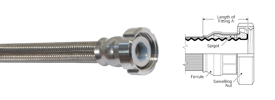
DIN11851 Male Fitting
| Nominal Hose Size |
*Fitting Length A (Male) |
*Fitting Length A (Female) |
Weight of Fitting |
| Male |
Female |
| in |
mm |
in |
mm |
in |
mm |
Kg |
Lbs |
Kg |
Lbs |
| 3/4 |
20 |
23/8 |
60 |
23/8 |
60 |
0.18 |
0.39 |
0.22 |
0.48 |
| 1 |
25 |
23/8 |
60 |
25/8 |
67 |
0.22 |
0.48 |
0.36 |
0.79 |
| 11/4 |
32 |
21/2 |
65 |
23/4 |
70 |
0.27 |
0.59 |
0.47 |
1.04 |
| 11/2 |
40 |
25/8 |
67 |
27/8 |
73 |
0.33 |
0.73 |
0.55 |
1.21 |
| 2 |
50 |
25/8 |
67 |
27/8 |
73 |
0.58 |
1.28 |
0.93 |
2.05 |
| 21/2 |
65 |
31/2 |
89 |
35/8 |
92 |
0.73 |
1.61 |
1.31 |
2.88 |
| 3 |
80 |
4 |
100 |
35/8 |
92 |
1.00 |
2.20 |
1.57 |
3.46 |
*Fitting Lengths listed are for Corroflon braided only hose grades (SS, PB, HB, KYB). Approximately 33% longer lengths apply to the rubber covered hose grades (RC, SI, FP).
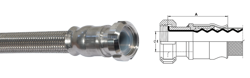
DIN11851 Female Fittings, not PTFE Lined
Description
DIN11851 Female Fittings, Non-Lined, are available in sizes 3/4”, 1”, 11/2”, 2”, 21/2”, 3” and 4”. Consult Aflex Hose for details.
Materials
Spigots in Grade 1.4571 (AISI 316 T), Nuts in Grade 304 SS, Ferrules, most in Grade 304 SS, some in Grade 316 SS.
| Nominal Hose Size |
ID (I) |
Fitting Length (A) |
Fitting Weight |
| in |
mm |
in |
mm |
in |
mm |
Kg |
Lbs |
| 1/2 |
13 |
16 |
0.63 |
48 |
1.89 |
0.18 |
0.40 |
| 3/4 |
20 |
20 |
0.79 |
73 |
2.87 |
0.24 |
0.53 |
| 1 |
25 |
26 |
1.02 |
74 |
2.91 |
0.41 |
0.90 |
| 11/4 |
32 |
32 |
1.26 |
89 |
3.50 |
0.52 |
1.15 |
| 11/2 |
40 |
38 |
1.50 |
101 |
3.98 |
0.75 |
1.65 |
| 2 |
50 |
50 |
1.97 |
105 |
4.13 |
1.11 |
2.45 |
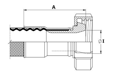
SMS & RJT Female Fittings
End Fitting Specification
- SMS generally to Swedish SMS1148 specification.
- RJT generally to British BS4825 Pt 5 specification.
Temperature and Pressure Ratings
- Pressures up to 10 Bar (150 psi)
- Temperatures up to 150˚C (302˚F)
End Fitting Materials
- Spigots in Grade 316L SS
- Nuts in Grade 304 SS
- Ferrules, most in Grade 304 SS, some sizes in Grade 316L SS
90˚ Elbows
PTFE Lined 90˚ elbow fittings are available for some sizes and grades.
SMS Female Fittings
| Nominal Size |
*Length A |
Outlet Dia. I |
Weight of Fitting |
| in |
mm |
in |
mm |
in |
mm |
Kg |
Lbs |
| 1 |
25 |
31/8 |
79 |
1 |
25 |
0.60 |
1.32 |
| 11/2 |
40 |
31/2 |
89 |
11/2 |
38 |
0.98 |
2.16 |
| 2 |
50 |
33/4 |
95 |
2 |
50 |
1.22 |
2.69 |
| 21/2 |
65 |
45/8 |
116 |
21/2 |
63 |
1.549 |
3.41 |
| 3 |
80 |
43/4 |
122 |
3 |
75 |
1.997 |
4.40 |
RJT Female Fittings
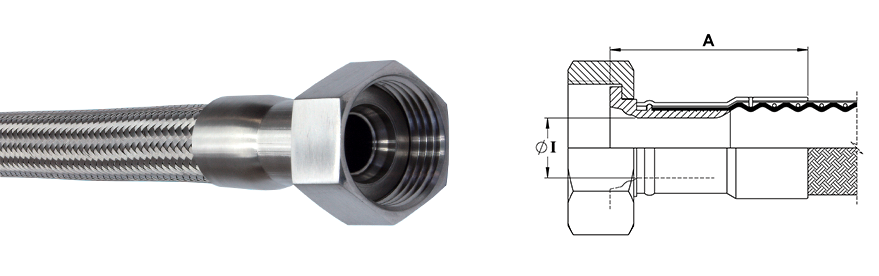
| Nominal Size |
*Length A |
Outlet Dia. I |
Weight of Fitting |
| in |
mm |
in |
mm |
in |
mm |
Kg |
Lbs |
| 1 |
25 |
2.68 |
68 |
0.80 |
20.24 |
0.27 |
0.6 |
| 11/2 |
40 |
3.78 |
96 |
1.25 |
31.75 |
0.49 |
1.08 |
| 2 |
50 |
3.90 |
99 |
1.75 |
44.45 |
0.67 |
1.48 |
| 21/2 |
65 |
4.09 |
104 |
2.25 |
57.15 |
0.78 |
1.72 |
| 3 |
80 |
4.21 |
107 |
2.63 |
66.7 |
0.89 |
1.96 |
*Fitting Lengths listed are for Corroflon braided only hose grades (SS, PB, HB, KYB). Approximately 33% longer lengths apply to the rubber covered hose grades (RC, SI, FP).
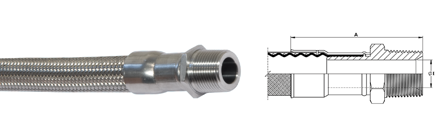
NPT and BSPT Fittings
End Fitting Specification
- NPT Taper Threads to American National Standard Pipe Taper Thread design to ANSI/AMSE B1.20.1
- BSPT Threads to British Standard Pipe Taper Thread design to BS21
Alternatives - Parallel Threads, Metric Threads and Others.
End Fitting Materials
- Fittings in Grade 316L SS
- Ferrules, most in Grade 304 SS, some sizes in Grade 316L SS
Alternatives - Fittings in Zinc Plated Carbon Steel
Fixed Male NPT or BSPT
| Nominal Hose Size |
*Fitting Length A |
Inside Diameter I |
Weight of Fitting |
| in |
mm |
in |
mm |
in |
mm |
Kg |
Lbs |
| 1/2 |
15 |
25/8 |
67 |
0.38 |
9.53 |
0.10 |
0.22 |
| 3/4 |
20 |
31/2 |
89 |
0.63 |
15.88 |
0.18 |
0.40 |
| 1 |
25 |
37/8 |
98 |
0.80 |
20.24 |
0.29 |
0.64 |
| 11/4 |
32 |
43/8 |
110 |
1.03 |
26.21 |
0.45 |
0.99 |
| 11/2 |
40 |
51/8 |
130 |
1.25 |
31.75 |
0.60 |
1.32 |
| 2 |
50 |
51/2 |
140 |
1.75 |
44.45 |
0.84 |
1.85 |
| 21/2 |
65 |
63/4 |
170 |
2.25 |
57.15 |
1.70 |
3.75 |
| 3 |
80 |
63/4 |
170 |
2.63 |
66.70 |
2.53 |
5.58 |
| 4 |
100 |
71/2 |
190 |
3.50 |
88.90 |
3.99 |
8.80 |
*Fitting Lengths listed are for Corroflon braided only hose grades (SS, PB, HB, KYB). Approximately 33% longer lengths apply to the rubber covered hose grades (RC, SI, FP).
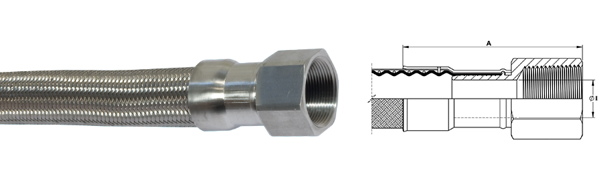
Fixed Female NPT
| Nominal Hose Size |
NPT or BSPT Thread Size |
*Fitting Length A |
Fitting Inside Diameter I |
Weight of Fitting |
| in |
mm |
in |
in |
mm |
in |
mm |
Kg |
Lbs |
| 1/2 |
13 |
1/2 |
2.72 |
69 |
0.38 |
9.53 |
0.18 |
0.40 |
| 3/4 |
20 |
3/4 |
3.54 |
90 |
0.63 |
15.88 |
0.22 |
0.49 |
| 1 |
25 |
1 |
3.82 |
97 |
0.80 |
20.24 |
0.33 |
0.73 |
| 11/2 |
40 |
1 1/2 |
4.96 |
126 |
1.25 |
31.75 |
0.75 |
1.65 |
| 2 |
50 |
2 |
5.16 |
131 |
1.75 |
44.45 |
1.06 |
2.34 |
*Fitting Lengths listed are for Corroflon braided only hose grades (SS, PB, HB, KYB). Approximately 33% longer lengths apply to the rubber covered hose grades (RC, SI, FP).
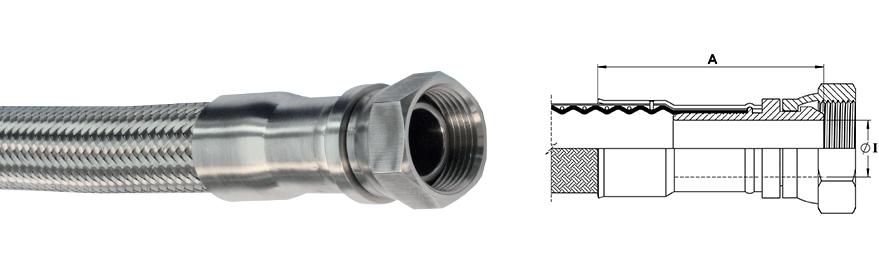
BSP 60° Cone Seat Female Fittings
End Fitting Specification
- BSPP Threads to British Standard Pipe Parallel Thread design to BS21, 60˚ Cone Seat design, or Flat Seat.
- Available in sizes up to 4"
Alternatives - Cone Seat Female Union Fittings can be supplied with a BSPP/BSPT Taper Male Adaptor if required.
End Fitting Materials
- Spigots in Grade 316L SS
- Nuts in Grade 316L SS
- Ferrules, most in Grade 304 SS, some sizes in Grade 316L SS
Alternatives
- Cone Seat Female Unions can be supplied in Zinc Plated Carbon Steel if required.
- Lug Nuts can be supplied in Gun Metal (Bronze) if required.
BSP 60˚ Cone Seat Female Union Fitting
| Nominal Hose Size |
NPT or BSPT
Thread Size |
*Fitting Length A |
Fitting Inside
Diameter I |
Weight of Fitting |
| in |
mm |
in |
in |
mm |
in |
mm |
Kg |
Lbs |
| 1/2 |
13 |
1/2 |
21/2 |
63 |
0.37 |
9.35 |
0.11 |
0.25 |
| 3/4 |
20 |
3/4 |
31/2 |
89 |
0.63 |
15.88 |
0.15 |
0.34 |
| 1 |
25 |
1 |
31/2 |
89 |
0.80 |
20.24 |
0.24 |
0.53 |
| 11/2 |
40 |
11/2 |
37/8 |
98 |
1.25 |
31.75 |
0.72 |
1.59 |
| 2 |
50 |
2 |
4 |
100 |
1.75 |
44.45 |
0.99 |
2.19 |
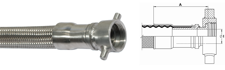
BSP Flat Face Lug Nut Female Fitting
| Nominal Hose Size |
BSPP Thread Size |
*Fitting Length A |
Fitting Bore Diameter I |
Weight of Fitting |
| in |
mm |
in |
in |
mm |
in |
mm |
Kg |
Lbs |
| 1 |
25 |
1 |
2.72 |
69 |
0.80 |
20.24 |
0.25 |
0.55 |
| 1 1/2 |
40 |
1 1/2 |
3.78 |
96 |
1.25 |
31.75 |
0.61 |
1.33 |
| 2 |
50 |
2 |
3.90 |
99 |
1.75 |
44.45 |
0.88 |
1.95 |
*Fitting Lengths listed are for Corroflon braided only hose grades (SS, PB, HB, KYB). Approximately 33% longer lengths apply to the rubber covered hose grades (RC, SI, FP)
JIC Fittings
End Fitting Specification
- SAE J514 37˚ Flare JIC Female Fitting
- 37˚ JIC Male-to-NPT Male/Female Adaptors
- NPT Threads to ANSI B2.1
Temperature and Pressure Ratings
Same Maximum Working Pressure and Temperature as for the relevant size of Corroflon Hose, in Specifications & Properties.
End Fitting Materials
- Spigots in Grade 316L SS
- Nuts in 316L SS
- Ferrules, most in Grade 304 SS, some sizes in Grade 316L SS
Note - Not usable with SAE 45˚ Flare fittings which have the same thread.
Alternatives - Can be supplied in other materials, such as zinc plated carbon steel, Hastelloy, Monel etc.
| Nominal Hose Size |
37˚ JIC Thread Size |
*Fitting Length A |
Hex Size
H |
Fitting Inner
Diameter I |
Weight of Fitting |
| in |
mm |
in |
in |
mm |
in |
mm |
in |
mm |
Kg |
Lbs |
| 1/2 |
13 |
3/4 - 16 |
2.13 |
54 |
0.88 |
22.2 |
0.38 |
9.5 |
0.11 |
0.24 |
| 3/4 |
20 |
1 1/16 - 12 |
2.99 |
76 |
1.25 |
31.7 |
0.63 |
15.9 |
0.15 |
0.34 |
| 1 |
25 |
1 5 /16 - 12 |
3.66 |
93 |
1.50 |
38.1 |
0.80 |
20.2 |
0.23 |
0.52 |
| 1 1/2 |
40 |
1 7/8-12 |
4.17 |
106 |
2.25 |
57.1 |
1.25 |
31.7 |
0.72 |
1.58 |
| 2 |
50 |
2 1/2 - 12 |
4.49 |
114 |
2.88 |
73.0 |
1.75 |
44.4 |
0.99 |
2.18 |
*Fitting Lengths listed are for Corroflon braided only hose grades (SS, PB, HB, KYB). Approximately 33% longer lengths apply to the rubber covered hose grades (RC, SI, FP).
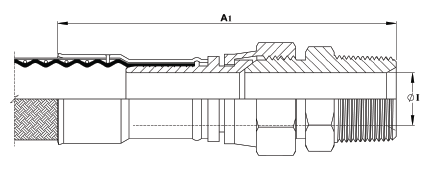
JIC to NPT Male Union (Including a JIC male-to-NPT male adaptor)
| Nominal Hose Size |
*Male Union Length A1 |
Weight of Fitting |
| in |
mm |
in |
mm |
Kg |
Lbs |
| 1/2 |
13 |
4.13 |
105 |
0.22 |
0.48 |
| 3/4 |
20 |
4.93 |
125 |
0.33 |
0.72 |
| 1 |
25 |
5.43 |
138 |
0.52 |
1.15 |
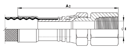
JIC to NPT Female Union (Including a JIC Male to NPT Female Adaptor)
| *Female Union Length A2 |
Fitting Inner Diameter I |
Weight of Fitting |
| in |
mm |
in |
mm |
Kg |
Lbs |
| 3.26 |
92 |
0.38 |
9.5 |
0.21 |
0.47 |
| 4.80 |
122 |
0.63 |
15.9 |
0.33 |
0.74 |
| 5.35 |
136 |
0.80 |
20.2 |
0.68 |
1.50 |
*Fitting Lengths listed are for Corroflon braided only hose grades (SS, PB, HB, KYB). Approximately 33% longer lengths apply to the rubber covered hose grades (RC, SI, FP).
PTFE Dip Pipe Fittings
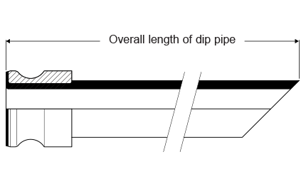
Fixed Dip Pipes
Description
Fixed Dip Pipes are fairly rigid, thick wall PTFE tubes, either straight or 90˚ elbowed, which are directly crimped to the end of Corroflon hoses. They are designed for insertion into drums, tanks and reaction vessels in order to suction drain (or inject) process fluids transferred through the hose.
Materials
- Standard dip pipes are in anti-static (AS) PTFE
- Ferrules, most in Grade 304 SS, some sizes in Grade 316L SS
How to order
Specify the size and material of the dip pipe, whether it is straight or 90˚ elbowed. Give the length of the straight leg of the dip pipe and the length of the rest of the hose assembly separately.
Maximum Working Pressures
Dip Pipes are normally only tested to 6 Bar Pressure, and are not suitable for use at pressures higher than 3 Bar. They are usable atnegative pressure up to -0.9bar vacuum.
If higher pressure ratings are required, consult Aflex Hose.
Lengths
Dip Pipes are supplied as standard in 1 metre straight lengths, but can be supplied in any length to individual requirements.
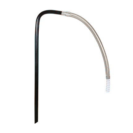 Fixed Dip Pipe (90˚ Elbow)
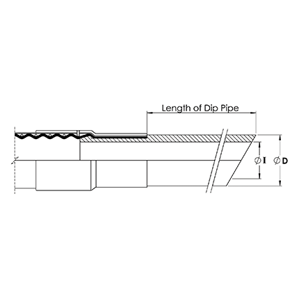 Fixed Dip Pipe (Straight)
| Approximate Dip Pipe Dimensions |
| Nominal Hose Bore Size |
Outside Diameter D |
Inside Diameter |
| in |
mm |
in |
mm |
in |
mm |
| 3/4 |
20 |
0.87 |
22 |
0.51 |
13 |
| 1 |
25 |
1.14 |
29 |
0.83 |
21 |
| 1 1/2 |
40 |
1.54 |
39 |
1.00 |
27 |
| 2 |
50 |
2.17 |
55 |
1.58 |
40 |
Detachable Dip Pipes
Description
As Fixed Dip Pipes above, but connected to the hose through an end fitting, not by crimping direct to the hose.
Design
A straight, or 90˚ elbowed anti-static PTFE Dip Pipe, fitted with a Flange or Cam & Groove Male PTFE Lined & Flared end fitting.
The most usual end fitting is a Cam Male (as shown), so the dip pipe can then be connected to a hose with a Cam Female end fitting.
Specifications
As above for Fixed Dip Pipes.
90° Elbow Fittings
PTFE Lined 90˚ Elbow Fittings
Scope
- All of the PTFE lined end fittings described on previous pages can be fitted as 90˚ elbow PTFE lined fittings to the design shown, to the sizes listed.
- All grades of hose can be used, except PB and KYB.
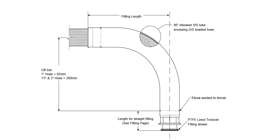
| Hose Bore Sizes |
Off-Set |
Fitting Length |
Weight of Fitting |
| mm |
mm |
Kg |
Lbs |
| 1" |
85 |
143 |
0.48 |
1.07 |
| 1 1/2" |
200 |
237 |
1.37 |
3.03 |
| 2" |
200 |
314 |
1.68 |
3.70 |
Non-Lined 90˚ Elbow Fittings
A 90˚ elbow attached to the hose can be supplied non-PTFE lined, as shown, for any size or grade of hose or type of fittings, to special order.
Labeling & Color Coding
Standard Labeling
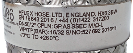
All Corroflon hose assemblies are labelled with the following information:
- Manufacturer’s Name
- Hose Size and Grade
- EN16643 and Year of Standard Publication
- EN16643 Electrical Property Grade
- Max. Working Pressure and Test Pressure
- Working Temperature Range*
- Unique Serial Number
- Month & Year of Manufacture
- Telephone Number
- CE Mark (if applicable)
*Note any restrictions on working pressure resulting from elevated temperatures
This information is normally laser-etched on to a loose stainless steel Ring mounted on the hose.
In some cases, at the discretion of Aflex Hose, the information may be etched on to a thin stainless steel plate which is clamped to the hose, or on to the end fitting ferrule at one end. This may be necessary for example, if the customer requires additional information which may not fit on to a Ring.
Customers may specify which labelling system they require, and may request additional information on the label.
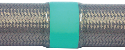
Streamline Tagging
This system is only applicable to the Silicone (SI) rubber covered grades of Corroflon that have a stainless steel (SS) braid.
A label and/or Color Code is placed around the silicone cover of the hose and then encapsulated by a transparent silicone that is formed into a thin streamlined cover.
Note: 1/2” size, Color Code only, no text.
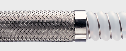
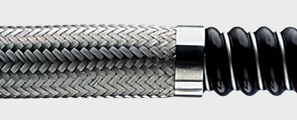
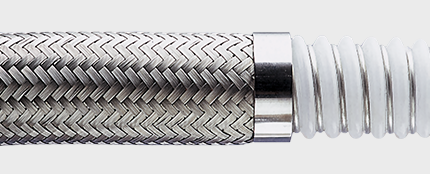
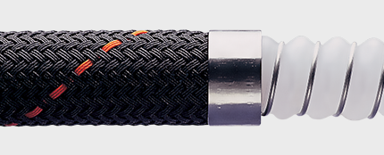
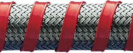
Color Coding
This system is applicable to all grades of Corroflon hose.
A coloured PTFE spiral strip is wound on to the hose. It can be left loose, or it can be encapsulated under a transparent, heat-shrunk polyolefin sleeve.
How to Order
The quantity, hose size, liner, braid, cover, protection system, length and fittings must be selected and specified in full.
EITHER by a full, written description. The hose grade can be specified by the code initials e.g. “Corroflon AS, SS, RC, DRC-300” defines an antistatic PTFE lined hose with an EPDM rubber cover over a SS braid, with a double rubber cover at both ends.
The quantity, length and fittings can then be written in - e.g. “4 off x 1” bore Corroflon, AS, SS, RC, DRC-300 hose x 3.00 metres long (10ft). Both ends non-lined ANSI 150# S/S Flanges”.
OR by Part Numbers.
Any special requirements relating to the hose construction, or information required on Tags, or Certificates, or special testing of requirements, must be specified in full on the enquiry or purchase order.
Selecting the Hose Grade
PTFE Liners include, Standard (GP) or Special Purpose (SP), both available either in natural white PTFE or in black, Antistatic PTFE (AS). There are four types of braid, Grade 304 stainless steel (SS) polypropylene (PB), Hastelloy (HB), PVDF or Kynar (KYB). Rubber covering and other external protection systems are also available.
A hose grade is specified by using the abbreviations given. For example, Bioflex AS,PB would describe a hose with an anti-static PTFE liner and a polypropylene braid.
Note: Most of the sizes of hose and fittings listed in this brochure are available as ex-stock items and are priced accordingly. However, when certain items have not been purchased in the last 12 months, they are no longer held in stock, and are only available to Special Order. Aflex Hose will advise accordingly when enquiries are placed for these items.
Selecting the End Fittings
Corroflon is available with a range of ‘standard’ end fittings, both integral PTFE lined and non-lined
Stainless Steel End Fitting Materials
Non-Lined Spigots - are all made from Grade 316L SS
PTFE Lined Spigots - are all made from Grade 316L or Grade 316C SS
Cam and Groove Female Fittings - are made from Grade 316C SS (Body) and 316L SS (Spigot)
Swivelling Nuts and Flanges - are all made from Grade 304 SS
Ferrules - most ferrules are made from Grade 304 SS, except some are made from Grade 316L SS - consult Aflex Hose if necessary.
The equivalent specification for the different Grades of Stainless Steel are listed below:
| Grade |
BS - British Standard |
AISI - American Standard or C = Casting Grade |
EN - European Norm |
| 316L SS |
BS 316 S11 |
AISI 316 L |
EN 1.4404 |
| 316C SS |
BS 316 C16 |
CF8M |
EN 1.440 |
| 304 SS |
BS 304 S15 |
AISI 30 |
EN 1.4301 |
Conditions of Sale
Corroflon hose and hose assemblies are only supplied on the basis that the customer has read and accepted the Conditions of Sale.
Selecting the Hose Length (see also Hose Usage Limitations)
Corroflon hose assemblies are made up to the specific lengths required. The hose length is taken as the length from the sealing face at one end of the hose to the same at the other end. The length tolerance is normally +5% / -0%. Closer tolerances are available to special order.
| Corroflon Hose Assembly Length Limitations |
| Nominal Size of Hose |
*Minimum Hose Assembly Length |
Maximum Hose Assembly Length |
| Used Straight |
Minimum at MBR |
| All Types |
TO, SS, PB, KYB |
RC |
| in |
mm |
in |
mm |
in |
mm |
in |
mm |
ft |
mtrs |
| 1/2 |
15 |
3 |
75 |
2.36 |
60 |
3.54 |
90 |
100 |
30 |
| 3/4 |
20 |
3 |
75 |
3.19 |
81 |
4.72 |
120 |
100 |
30 |
| 1 |
25 |
3 |
75 |
14.33 |
110 |
6.50 |
165 |
100 |
30 |
| 1 1/4 |
32 |
3 |
75 |
5.08 |
129 |
7.64 |
194 |
100 |
30 |
| 1 1/2 |
40 |
3 |
75 |
6.22 |
158 |
9.29 |
236 |
100 |
30 |
| 2 |
50 |
3 |
75 |
8.66 |
220 |
12.99 |
330 |
100 |
30 |
| 2 1/2 |
65 |
4 |
100 |
11.02 |
280 |
16.54 |
420 |
65 |
20 |
| 3 |
80 |
4 |
100 |
14.25 |
362 |
21.34 |
542 |
65 |
20 |
| 4 |
100 |
12 |
300 |
18.58 |
472 |
27.83 |
707 |
32 |
10 |
| 6 |
150 |
12 |
300 |
37.13 |
943 |
55.67 |
1414 |
28 |
8 |
* Listed minimum lengths are for the Corroflon Hose only, and DO NOT INCLUDE THE LENGTHS OF THE FITTINGS AT EACH END.
These must be found from the end fitting pages and added to calculate the minimum length of the hose assembly.
Used straight with fittings in line.
Only minimal vibration permitted.
Part Nos
If required, Corroflon Hose Assembly can be defined by an individual Part Number, made up of 7 entries as below:
1)
| Hose Size |
Size Part No. |
| 1/2” |
08 |
| 3/4” |
12 |
| 1” |
16 |
| 11/4” |
20 |
| 11/2” |
24 |
| 2" |
32 |
| 2 1/2" |
40 |
| 3" |
48 |
| 4" |
64 |
| 6" |
96 |
2)
| Hose Type |
Type Part No |
| Corroflon GP (Natural PTFE Liner) |
CFLN/GP |
| Corroflon AS (Antistatic PTFE Liner) |
CFLN/AS |
3)
| Braid and Cover |
| Table Only |
TO |
| Stainless Steel Braid
|
SS |
| Polypropylene Braid
|
PB |
| Hastelloy Braid
|
HB |
| Kynar (PVDF) Braid
|
KYB |
| Black EPDM Rubber Cover (on SS)
|
RC |
| Transparent Silicone Rubber (on SS)
|
SI |
| Red Fireproof EPDM Rubber (on SS)
|
FP |
4)
| External Protection Systems |
| No External Protection System
|
OO |
| S/S Wire Protection Coil |
SR |
| Rubber Anti-Scuff Rings |
SR |
| Safegard HDPE Spiral Wrap |
SG |
5)
| Length |
| The overall hose length between the sealing faces at each end is given as the Length Part No, either in decimal Metres followed by “m” or Inches followed by “in”. |
6 & 7)
Assembled End Fitting Description
* All Components in Stainless Steel
|
End Fitting Part No. |
| JIC Female |
02
|
| Fixed Male Pipe, NPT Thread |
03 |
| Fixed Male Pipe, BSPT Thread |
03/B |
| Fixed Female Pipe, NPT Thread |
06 |
| JIC-to-NPT Male Union |
08 |
| JIC-to-Female Union |
08F |
Straight Sanitary Tri Clamp, 1.984” Diameter
0.870” Exit Diameter (Standard)
1.370” Exit Diameter (Step-Up) |
-
10
10/S |
Straight Mini Sanitary Tri Clamp, 0.984” Diameter
0.370” Exit Diameter (Standard)
0.625” Exit Diameter (Step-Up) |
-
11
11/S |
| *ANSI 150# Swivelling Flange Non-Lined |
12 |
| DIN PN 10/16 Swivelling Flange Non-Lined |
12/PN |
| *ANSI 150# Swivelling Flange, PTFE Lined |
12L |
| DIN PN 10/16 Swivelling Flange, PTFE-Lined |
12/PN |
| Cam and Groove, Locking Arm Swivelling Female, Non-Lined |
16 |
| Cam and Groove Locking Arm Swivelling Female, PTFE Lined |
16L |
| Cam and Groove Male, Non-Lined |
17 |
| Cam and Groove Male, PTFE Lined |
17L |
| DIN 11851 Female, PTFE Lined |
23L |
| DIN 18851 Male, PTFE Lined |
24L |
| SMS Female, PTFE Lined |
26L |
| RJT Female, Non-Lined |
27 |
| BSPP Cone Seat Female |
33 |
| BSP Lug Nut Female |
34 |
*For flange only, Carbon Steel Zinc Plated, add “/ZP” or Epoxy coated add “/EC”
Notes:
- ELBOWS: Elbow Fittings for all types are indicated by adding “/90˚” for 90˚ elbows.
- END PROTECTION: If one of the rubber end protection systems is required, for one or both ends, please define the requirement in writing in addition to the Part Number.
TRICLAMPS: For “Hot Formed” PTFE Lined Triclamps add “/HF”
Example:
A ¾” bore Corroflon GP, RC Hose Assembly with an Antistatic PTFE Liner and an outer Safegard sleeve.
End (1) - a 3/4” ANSI 150# Swivel Flange, PTFE Lined
End (2) - a Cam and Groove Swivelling Female, PTFE Lined
Length - 4ft 6 inches
Hose Assembly Part No. = 12 - CFLN/AS - RC - SG - 54in - 12L - 16L
Additional Requirements
Any additional requirements which are not included in the Part Number must be written out in full in the Order, including any special labelling or colour coding
* Note - if one of the rubber end protection systems is required, for one or both ends, please define the requirement in writing in addition to the Part Number.
Quality Assurance & Certifications
BS EN ISO 9001:2008
Aflex products are all manufactured in accordance with BS EN ISO 9001: 2008 Quality Management Systems independently assessed and registered by The British Standards Institution (BSI).
EN 16643
Corroflon meets the requirements of EN 16643 (C), which include the electrical and electrostatic requirements of hose assemblies.
TS16949
Aflex Hose Ltd manufactures PTFE flexible hose for the automotive industry in accordance with TS16949 and is assessed and certified by The British Standards Institution (BSI).
ISO 14001:2015
Aflex Hose Ltd have been successfully assessed to the requirements of ISO 14001, by the British Standards Institution (BSI). By gaining this accreditation Aflex Hose Ltd are demonstrating our commitment to reducing our impact on the environment.
USP Class VI and ISO 10993-5, 6, 10 & 11 guidelines
Natural and Antistatic PTFE Hose Liners, Platinum Cured Silicone Rubber Covers (White and Clear) and EPDM Rubber Cover (Blue) have been independently tested in accordance with USP protocols and are found to conform to the requirements of USP Class VI Chapter <88>.
Natural and Antistatic PTFE Hose Liners and Platinum Cured Silicone Rubber Covers (White and Clear) have also been tested in accordance with USP protocols and are found to conform to the requirements of USP Class VI <87>, the L929 MEM Elution Test and are considered non-cytotoxic.
FDA
The Materials used to manufacture the natural PTFE Tube liner conforms to FDA 21 CFR 177.1550, and the antistatic PTFE liner conforms to FDA 21 CFR 178.3297.
Pharmaceutical Manufacturers Approvals
Most of the major pharmaceutical manufacturing companies in the world have audited and/or approved Aflex Hose as a Hose Supplier.
BPSA Leachables and Extractables Testing
Aflex Hose Natural and Antistatic PTFE Hose Liner Tube has been independently tested in accordance with BPSA recommendations, and found to be satisfactory.
Copies of the Test Report are available for specific assessments to be made.
CE Marking (Europe only)
Aflex has been assessed by The British Standards Institution (BSI) and found to comply with the Pressure Equipment Directive 2014/68/EU Conformity Assessment Module D1, approved to CE Mark applicable hose products, accompanied by a Hose Usage Data Sheet, and a Declaration of Conformity.
Attestations of Conformity to ATEX Directive 2014/34/EU (Potentially Explosive Atmospheres)
Available for hose assemblies for components used in Gas Zones 1 & 2 and Dust Zones 21 & 22, when applicable.
Material Certification to EN10204
Available for all the hose or hose assembly components.
Certificates of Conformity to BS EN ISO/IEC 17050
Are available for all products.
Hose Testing
Each assembly is pressure tested to 2.0 times maximum working pressure before despatch, and pressure test certificates can be supplied.
Fire Resistance to BS5173 Section 103.13 Part 6.2 and 6.3
RC Grade Corroflon hose assemblies are “Fire Resistant”. If DRC-300 is added at both ends, the assemblies are upgraded to “Fire Proof”.
Special Usage Conditions
Cleaning & Sterilising Systems - CIP, SIP and Autoclave
CIP & SIP – PTFE liner tubes are chemically resistant to all CIP, SIP and Autoclave conditions. The primary consideration is whether the cleaning and purging cycle is likely to develop an electrostatic charge on the internal surface of the liner, in which case AS (Anti-Static) grade hose is required.
AS grade hose and Electrostatic charge generating systems are fully described in the hose liner section.
CIP systems using high electrical resistivity solvents like Toluene will require AS grade hose.
Another electrostatic generation problem arises when wet steam is used, or when the cleaning fluids or WFI are purged out of the line using nitrogen, compressed air or another gas, because droplets of liquid or water in the gas then generate a multi-phase condition until they are cleared out, which will generate a static charge, and so will require AS grade hose.
In static generating applications where AS grade hose is not acceptable due to the black PTFE liner, alternative solutions are available – please consult Aflex Hose for advice.
Autoclave – Autoclave sterilisation does not normally involve any high flow rates through the hose bore, so static generation is not a problem. Aflex hose grades GP and AS, with SS or HB braids are fully resistant to all autoclave conditions throughout the service life of the hose.
The rubber covered grades EPDM, (RC) and Silicone Rubber (RC, SI) are able to withstand at least 100 x 30 minute autoclave cycles at relatively high autoclave temperatures (121°C, 250°F or 135°C, 275°F). Consult Aflex Hose for more specific information.
PTFE Hose-Use with Alkali Metals, Halogens and Halogen containing Chemicals
PTFE hose liners react chemically with Fluorine, Chlorine Trifluoride and molten Alkali Metals.
When PTFE lined hose is used to carry Chlorine or Bromine, either as gasses or fluids, they will diffuse into and through the PTFE liner wall thickness. Trace quantities will then combine with atmospheric moisture to corrode any braid/rubber outer coverings.
Heavily halogenated chemicals, like Hydrogen Fluoride, Hydrogen Chloride, Phosgene (Carbonyl Chloride) Carbon Tetrachloride and other organic chemicals with a high halogen content can also be absorbed and transmitted through the PTFE liner tube.
Other “Penetrating” Fluids and Gases
Sulphur Trioxide, Methyl Methacrylate, Caprolactam and Glacial Acetic Acid are some other chemicals which can be absorbed and transmitted through the PTFE liner tube wall.
Generally, however, as a hydrophobic (non-wetting) material, PTFE is very resistant to the absorption of chemicals. In some cases, PTFE has superior resistance to diffusion, for example to the diffusion of automotive fuels, in comparison with all other plastics and rubbers.
Gas/Fluid Cycling
There are some applications where the fluid passing through the hose turns into a gas, then back into a fluid, then into a gas etc, in a cyclic sequence.
This is normally associated with changes in temperature and/or pressure. For complex reasons these conditions are extremely damaging to the hose liner, whatever material it is made from.
For example, hoses are sometimes used to pass steam, water, steam etc into rubber moulding presses, in order to heat the mould, then rapidly cool it before reheating in the next cycle. Hoses of all types fail rapidly in such an application and PTFE lined hoses are no exception.
Please contact Aflex Hose for further information if these conditions apply.
Connecting Assemblies for Use in Applications
The lengths of hose assemblies and their configuration in use when connected into the application must always be in accordance with the Hose Configuration information at the end of this product literature.
When being connected for use in applications, the end fittings on hose assemblies must be connected to correct mating parts in the correct way, using the correct tools, spanners, clamps, nuts and bolts etc. The connections must be sufficiently tightened to ensure that the joint is leak free but not be over tightened as this can damage the sealing surfaces, especially with PTFE lined and flared end fittings.
In applications involving the transfer through the hose of expensive or dangerous fluids or gases, the hoses and connections must be pressure tested in situ before being put in to service. This should be done with some harmless media to 2.0 times the maximum working pressure of the hose assembly, as stated in the product literature.
If in doubt please contact Aflex Hose for advice.
Special Applications
Aflex Hose PTFE lined hose products are not rated as suitable for use in the following, special applications:
- All Radioactive Applications involving high energy radiation, including Gamma radiation (degrades PTFE)
- All Medical Implantation Applications.
- All Aerospace Applications.
Silicone-Free Application Requirements
Some applications, particularly paint manufacturing plants, and other specialised applications require that hoses do not include any silicone containing materials in their manufacture (which is possible), or sometimes that hoses are 100% Silicone Free (which may not be possible). Customers or Distributors must identify and define any such requirements in writing on all enquiries/orders.
Configure for Bend Radius
Hose Configuration Requirements
Hose Assemblies are usually connected at both ends in service. They may then either remain in a fixed, or static configuration or in a flexing, or dynamic configuration.
Whether static or dynamic, the First Rule concerning the configuration of the hose is that the bend radius of the hose must never be less than the Minimum Bend Radius (MBR) for the hose as listed in the relevant hose brochure.
The most common situation when this is likely to occur is when the hose is flexed at the end fitting, with stress being applied to the hose at an angle to the axis of the end fitting. Typically, this happens either because the length of the hose is too short, or because the weight of the hose plus contents creates a stress at an angle to the end fitting.
The Second Rule, therefore, if possible, is to design the configuration to ensure that any flexing in the hose takes place away from the end fittings.
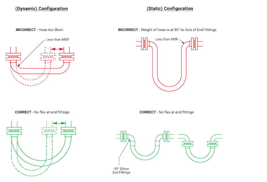
Configure for Abrasion & Torque
The Third Rule is that the hose configuration should always be designed, and supported where necessary, to avoid any possibility of external abrasion.
In some cases, the length, configuration and angle of the hose can be designed to avoid abrasion. In others, static or moving support frames or support wheels are required.
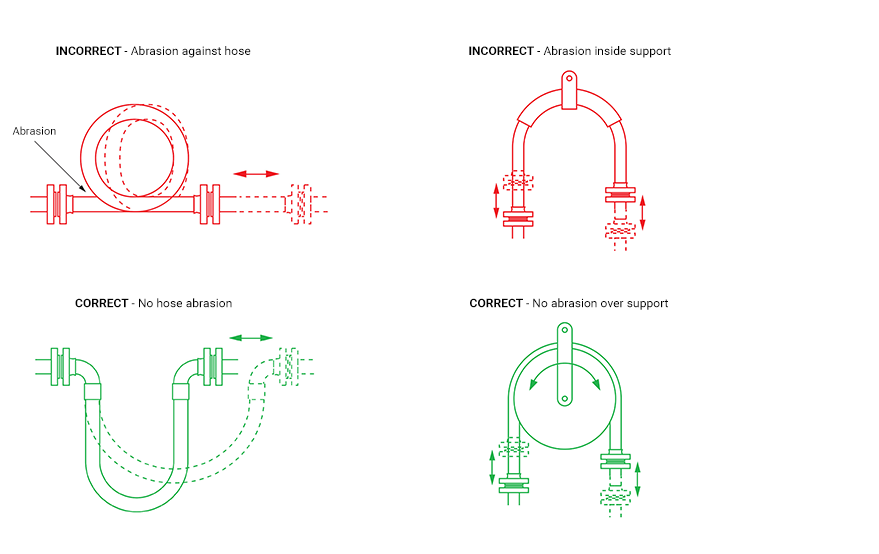
The Fourth Rule is that the hose must not be subjected to torque, either during connection, or as a result of the flexing cycle.
Torque (twist) in the hose can be applied during connection if the hose is accidentally twisted, or if the second end being connected is a screwed connection, and the hose is subjected to torque during final tightening.
In a flexing application, if any flexing cycle of the hose occurs in 3 dimensions instead of 2, then torque will also occur:
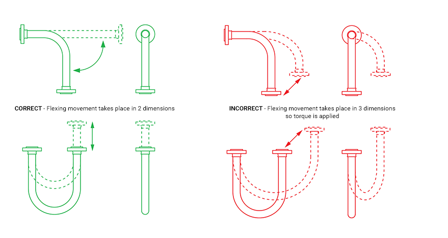
Length Calculation
Calculating the Hose Length
The formula for calculating the bent section of the hose length around a radius is derived from the basic formula that the circumference of a circle = 2πR, where R = the radius of the circle, and π = a constant, = 3.142.
So, if the hose goes around a 90˚ bend, which is 1/4 of a full circumference, and the radius of the bend is R, then the length of the hose around the bend is = 1/4 x 2πR. Or half way round, in a U-shape, = 1/2 x 2πR.
Note: In calculating the length of a hose assembly, the (non-flexible) length of the end fittings must be added in, also the length of any straight sections of hose, as in the following example:
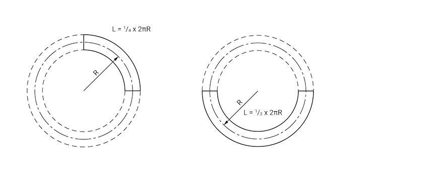
Example:
To calculate the length for a 2” bore size hose with flange end fittings, to be fitted in a 90˚ configuration with one leg 400mm long, the other 600mm long.
Length of Bent Section (yellow) = 1/4 x 2πR (334) = 1/4 x 2 x 3.142 x 334 = 525mm
Length of top, Straight Section, including the top end fitting length = 600 - 334 = 266mm
Length of bottom end fitting = 66mm
Total length of Hose Assembly = 525 + 266 + 66 = 857mm
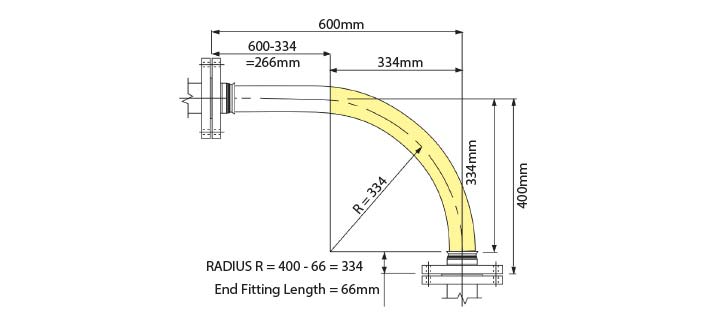
Things to consider:
- A hose will normally take the longest radius available to it to go around a corner, not the MBR! Also - always remember to include the non-flexible end fitting lengths.
- In dynamic applications, remember to always calculate the lengths for the most extended configuration during the flexing cycle, not the least extended.
- If the configuration is simply too complex for calculation, then obtain a length of flexible tubing of some kind, mark on paper, or a wall, or floor, or both where the connection points will be relative to each other, scaled down if necessary, then manually run the flexible tubing between them with full radii round bends. Measure the extended length, then scale up if necessary to determine the approximate length of the hose.
If in doubt, consult Aflex Hose.
|