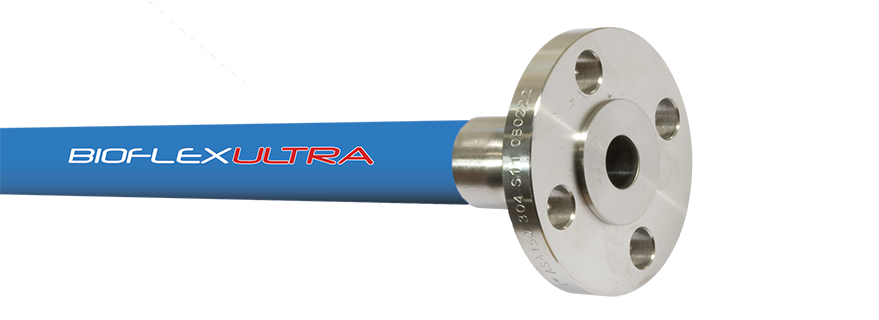
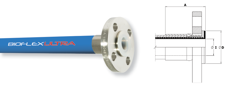
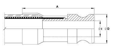
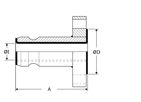
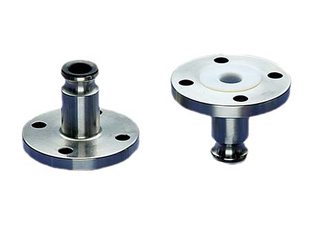
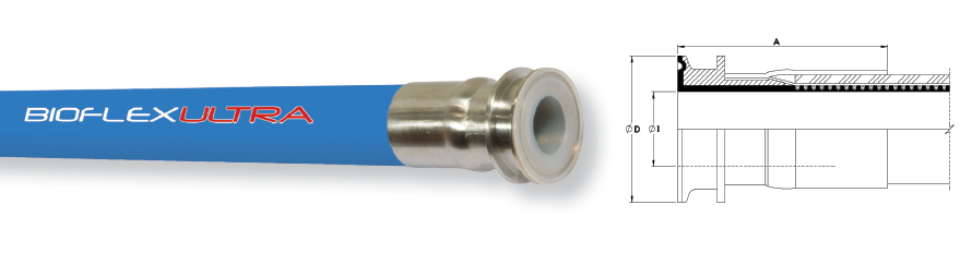
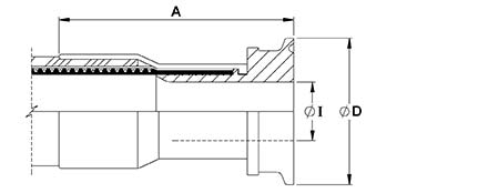
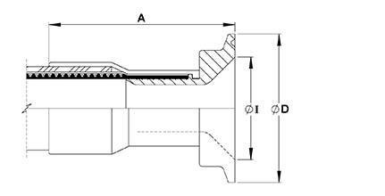
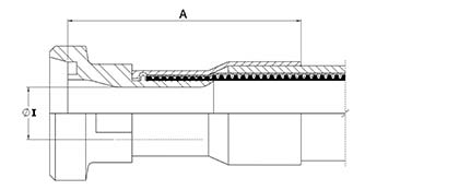
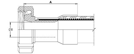
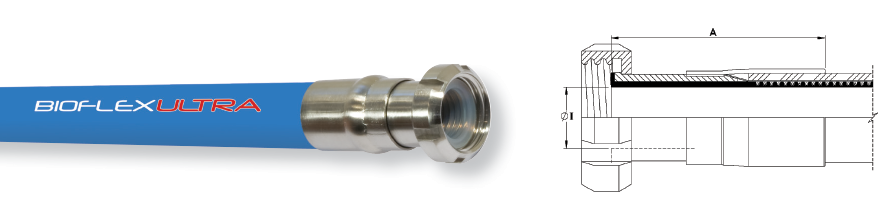
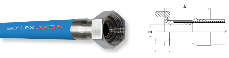
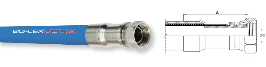
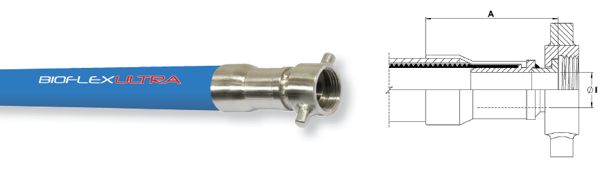
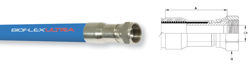
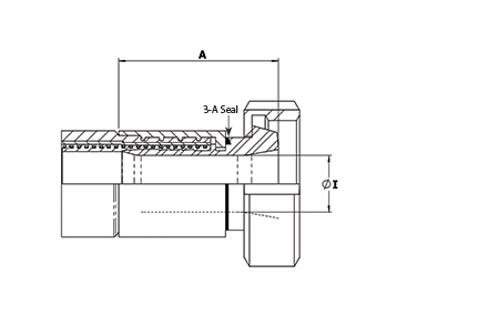
Non-Lined Swivel Flange Fittings
Flange Specifications
- ANSI B16.5 (also ASME B16.5) Class 150# and 300#
- *DIN PN10, PN16 and PN40
- JIS 10K
- Other Pressure Ratings and Flange Specifications are also available.
*DIN PN10, PN16 and PN40 Flanges all have the same dimensions, and so are fully interchangeable
End Fitting Materials
- Flanges normally in Grade 304 SS, or Grade 316 SS if required
- Flange Retainers in Grade 316L SS
- Ferrules, most in Grade 304 SS, some sizes in Grade 316 SS
Alternative Options for Flange Component only:
Surface Finish
- All surface finishes are to ASME BPE-SF-O (No finish required).
- If a specified finish on a particular surface is required, please state on the enquiry and order.
Maximum Pressure Ratings
- ANSI 150# = 16 Bar (230 psi),
- ANSI 300# = 41.4 Bar (600 psi)
- DIN PN10 = 10 Bar (145 psi),
- DIN PN16 = 16 Bar (230 psi)
- DIN PN40 = 40 Bar (580 psi)
|
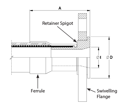
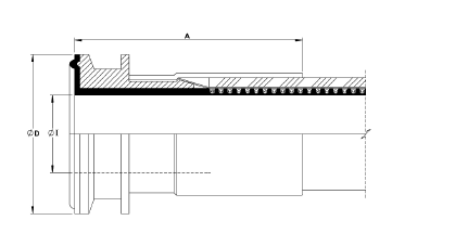
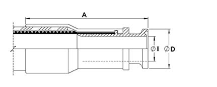
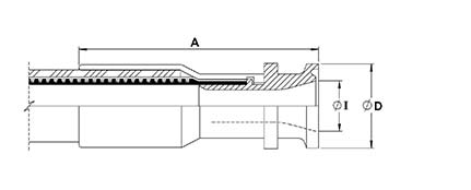
The above drawing relates to sizes 1", 1 1/2", 2" |
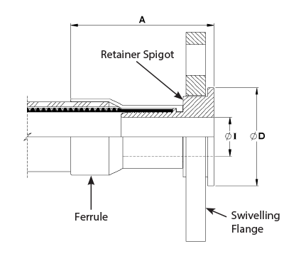
The above drawing relates to all other sizes |
| Nominal Hose Size |
*Fitting Length A
ASA150 |
Flared Diameter D
ASA150 |
Fitting Inside Diameter I
ASA150 |
Weight of Fitting |
†3A |
| in |
mm |
in |
mm |
in |
mm |
in |
mm |
kg |
lbs |
|
| 1/2 |
13 |
2.80 |
71 |
1.38 |
35.00 |
0.38 |
9.53 |
0.77 |
1.69 |
- |
| 3/4 |
20 |
3.15 |
80 |
1.69 |
42.90 |
0.63 |
15.88 |
1.061 |
2.35 |
√ |
| 1 |
25 |
3.27 |
83 |
2.00 |
50.80 |
0.79 |
20.24 |
1.361 |
3.00 |
√ |
| 11/4 |
32 |
3.97 |
101 |
2.50 |
63.5 |
1.03 |
26.2 |
2.53 |
5.58 |
√ |
| 1 1/2 |
40 |
4.09 |
104 |
2.87 |
73.00 |
1.25 |
31.75 |
2.49 |
5.50 |
√ |
| 2 |
50 |
4.17 |
106 |
3.62 |
92.00 |
1.75 |
44.45 |
3.57 |
7.87 |
√ |
| **21/2 |
65 |
3.70 |
94 |
4.13 |
105.00 |
2.25 |
57.15 |
4.36 |
9.59 |
√ |
| **3 |
80 |
3.74 |
95 |
5.00 |
127.00 |
2.63 |
66.7 |
6.02 |
13.24 |
√ |
| Nominal Hose Size |
*Fitting Length A
PN10/16 |
Flared Diameter D
PN10/16 |
Fitting Inside Diameter I
PN10/16 |
Weight of Fitting |
†3A |
| in |
mm |
in |
mm |
in |
mm |
in |
mm |
kg |
lbs |
|
| 1/2 |
13 |
2.87 |
73 |
1.77 |
45.00 |
0.38 |
9.53 |
0.77 |
1.69 |
- |
| 3/4 |
20 |
3.27 |
83 |
2.28 |
58.00 |
0.63 |
15.88 |
1.061 |
2.35 |
√ |
| 1 |
25 |
3.58 |
91 |
2.68 |
68.00 |
1.12 |
28.50 |
1.361 |
3.00 |
√ |
| 11/4 |
32 |
4.17 |
106 |
3.07 |
78.00 |
1.03 |
26.2 |
2.29 |
5.05 |
√ |
| 11/2 |
40 |
4.53 |
115 |
3.49 |
88.00 |
1.70 |
43.10 |
2.49 |
5.50 |
√ |
| 2 |
50 |
4.49 |
114 |
4.02 |
102.00 |
2.15 |
54.50 |
3.57 |
7.87 |
√ |
| **21/2 |
65 |
3.62 |
92 |
4.80 |
122.00 |
2.25 |
57.15 |
4.58 |
10.07 |
√ |
| **3 |
80 |
3.74 |
95 |
5.43 |
138.00 |
2.63 |
66.70 |
6.03 |
13.26 |
√ |
* Fitting lengths listed are for Bioflex Ultra RC, SI and BK hose grades. Shorter lengths apply for other hose grades.
**21/2" and 3" sizes are only available as Direct Crimp Fittings.
† 3A - Clean out of place (COP) only. The 3-A Fittings on this page are DC design only, see 3-A Sanitary Fittings for specifications.
 |
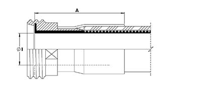
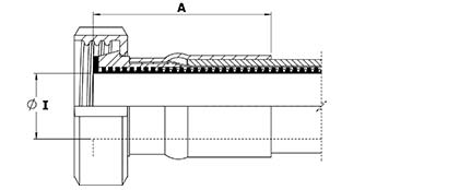
PTFE LINED FLANGE FITTINGS
Flange Specifications
- ANSI B16.5 (also ASME B16.5) Class 150# and 300#
- *DIN PN10, PN16 and PN40
- JIS 10K
- Other Pressure Ratings and Flange Specifications are also available.
*DIN PN10, PN16 and PN40 Flanges all have the same dimensions, and so are fully interchangeable
Maximum Pressure Ratings for Flange Fittings
- ANSI 150# = 16 Bar (230 psi), ANSI 300# = 41.4 Bar (600 psi)
- DIN PN10 = 10 Bar (145 psi), DIN PN16 = 16 Bar (230 psi)
- DIN PN40 = 40 Bar (580 psi)
End Fitting Materials
- Flanges in Grade 304 SS
- Flange Retainers in Grade 316L SS
- Ferrules, most in Grade 304 SS, some sizes in Grade 316 SS
Alternative Options for Flange Component only
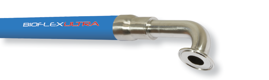
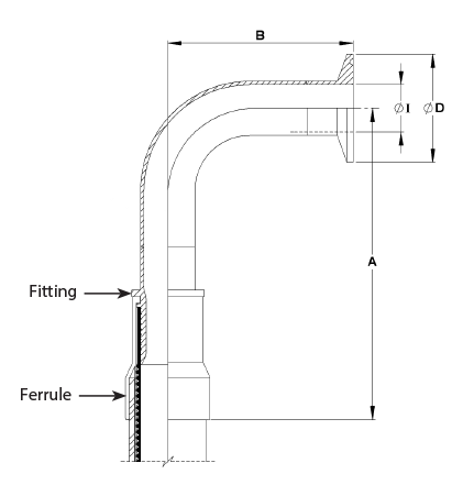
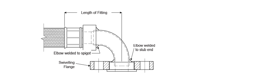
90° Elbow Flange Fittings
- 90˚ Elbow Integral PTFE lined Flange Fittings are available for sizes 1”, 11/2” and 2”
|
| Nominal Hose Size |
*Fitting Length A
(Bioflex Ultra RC)
ASA |
*Fitting Length A
(Bioflex Ultra RC)
PN |
**Flared Diameter D |
Fitting inside Dia. & Hose Bore I |
Recommended Bolt Tightening Torques |
Weight of Fitting |
†3A |
| ANSI 150# |
DIN PN10/16 |
| in |
mm |
in |
mm |
in |
mm |
in |
mm |
in |
mm |
in |
mm |
ft.lbs |
mtr.kgs |
kg |
lbs |
|
| 1/2 |
13 |
2.24 |
57.0 |
2.28 |
58 |
1.25 |
32 |
1.25 |
32 |
1/2 |
13.0 |
8 |
1.10 |
0.54 |
1.20 |
- |
| 3/4 |
20 |
1.89 |
48.0 |
1.93 |
49 |
1.69 |
43 |
1.97 |
50 |
3/4 |
19.4 |
8 |
1.10 |
0.88 |
1.90 |
√ |
| 1 |
25 |
2.40 |
61.0 |
2.48 |
63 |
2.00 |
50 |
2.50 |
63 |
1 |
25.7 |
10 |
1.40 |
0.96 |
2.10 |
√ |
| 11/4 |
32 |
2.24 |
57.0 |
2.32 |
59 |
2.48 |
63 |
3.10 |
78 |
11/4 |
32.4 |
12 |
1.66 |
1.15 |
2.53 |
√ |
| 11/2 |
40 |
2.36 |
60.0 |
2.44 |
62 |
2.875 |
73 |
3.50 |
88 |
11/2 |
38.9 |
15 |
2.10 |
1.75 |
3.80 |
√ |
| 2 |
50 |
2.72 |
69.0 |
2.91 |
74 |
3.625 |
92 |
4.00 |
102 |
2 |
51.6 |
25 |
3.50 |
2.70 |
5.95 |
√ |
| 21/2 |
65 |
4.86 |
123.5 |
4.86 |
123.5 |
4.13 |
105 |
4.80 |
122 |
21/2 |
63.7 |
30 |
40.18 |
4.21 |
9.26 |
√ |
| 3 |
80 |
5.17 |
131.4 |
5.17 |
131.4 |
5.00 |
127 |
5.00 |
127 |
3 |
76.8 |
40 |
53.94 |
4.75 |
10.44 |
√ |
* fitting lengths listed are for Bioflex Ultra RC, SI and BK hose grades. Shorter lengths apply for other hose grades.
** The listed Flare Diameters for 1/2", 3/4" and 1" are not full size due to limitations on PTFE flare diameters.
† 3A - Clean out of place (COP) only. For more information see 3-A Sanitary Fittings.
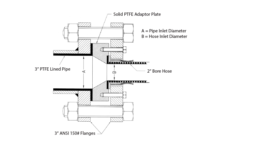
Example: a 2” hose to 3” ANSI 150# PTFE Lined Flange Joint |
‘Step-Up’ PTFE Lined Flange Fitting Design for Bioflex Ultra Hose
Because Bioflex Ultra Hose has better flow rates than some larger bore sizes of Convoluted PTFE hose, it represents a superior alternative when fitted with the larger size flanges in some applications.
It is, however, necessary to also “Step-Up” the PTFE-lined bore, to ensure a diameter match with the mating connector.
This is best achieved using a solid PTFE Adaptor Plate, as shown in the drawing.
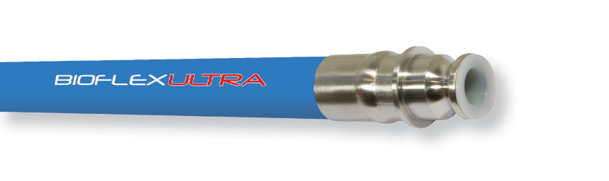
BIOFLEX FEMALE CAM & GROOVE FITTINGS PTFE LINED and NON-LINED
End Fitting Specifications
- Generally in accordance with A-A-59326 (replaces MIL-C-27487) and EN14420-1 (replaces DIN 2828), and all are fully interchangeable.
End Fitting Materials
- Spigot in Grade 316L SS
- Body in Grade 316C SS
- Ferrules, most in Grade 304 SS, some sizes in Grade 316L SS
- Standard Gasket is Buna N (Nitrile) Rubber.
- FEP encapsulated Silicone Rubber Gaskets also available.
Surface Finish: (Non-Lined Fittings only)
- All surface finishes are to ASME BPE-SF-O (No finish required).
- If a specified finish on a particular surface is required, please state on the enquiry and order.
Temperature and Pressure Ratings
- When used with a Buna N Gasket all sizes up to 16 Bar (230 psi) and up to a maximum temperature of 65˚C (149˚F)
- When used with FEP, Fluoro Rubber or other encapsulated gaskets all sizes up to 10 Bar (145 psi) and up to a maximum temperature of 204˚C (400˚F).
90˚Elbow Cam & Groove Fittings (PTFE Lined Only)
- 90˚ Elbow Integral PTFE lined Cam & Groove Fittings are available for sizes 1”, 11/2” and 2” - see 90˚ Elbow Fittings.
Notes: For Integral PTFE Lined Fittings Only
- FEP Gaskets require higher clamping forces to flatten the Seal and make the joint. This is made easier by “pre-setting” these gaskets by clamping Polypropylene Cam Male Inserts to the assembled fittings, which must then be kept in place during storage, until use.
- Any Customer’s Own “Special” Gaskets must be pre-supplied to Aflex for special assembly and testing of hose assemblies, to ensure suitability.
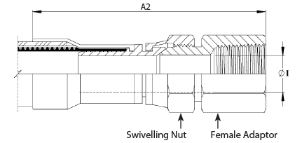
SWIVELLING, LOCKING ARM FEMALE CAM AND GROOVE FITTING - NON-LINED |
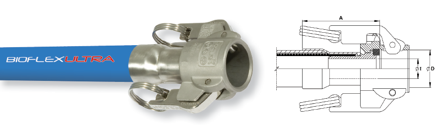 |
| Nominal Hose Size |
*Fitting Length A (RC) |
Cam Sleeve Inside Dia. D |
Fitting Inside Diameter I |
Weight of Fitting |
| in |
mm |
in |
mm |
in |
mm |
in |
mm |
Kg |
Lbs |
| 3/4 |
20 |
3.22 |
82.0 |
1.260 |
32 |
0.625 |
15.88 |
0.54 |
1.19 |
| 1 |
25 |
3.39 |
86.5 |
1.456 |
37 |
0.797 |
20.24 |
0.71 |
1.56 |
| 11/4 |
32 |
3.86 |
98.0 |
1.810 |
46 |
1.03 |
26.21 |
1.20 |
2.64 |
| 11/2 |
40 |
3.97 |
101.0 |
2.126 |
54 |
1.25 |
31.75 |
1.23 |
2.71 |
| 2 |
50 |
4.09 |
104.0 |
2.520 |
64 |
1.75 |
44.45 |
1.52 |
3.35 |
| **21/2 |
65 |
2.99 |
76.0 |
3.010 |
76.5 |
2.25 |
57.15 |
1.42 |
3.12 |
| **3 |
80 |
2.80 |
71.0 |
3.630 |
92.2 |
2.63 |
66.70 |
1.88 |
4.14 |
Fixed or Swivelling, Locking Arm Female Cam and Groove Fitting
- Integral PTFE Lined |
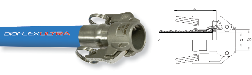 |
| Nominal Hose Size |
Fitting Length A (RC) |
Cam Sleeve Inside Dia.D |
Fitting inside Diameter I |
Weight of Fitting |
| in |
mm |
in |
mm |
in |
mm |
in |
mm |
Kg |
Lbs |
| 3/4 |
20 |
2.155 |
54.75 |
1.260 |
32.0 |
0.76 |
19.4 |
0.42 |
0.93 |
| 1 |
25 |
2.716 |
69.00 |
1.456 |
37.0 |
1.01 |
25.7 |
0.59 |
1.30 |
| 11/4 |
32 |
2.560 |
65.50 |
1.810 |
46.0 |
1.26 |
32.0 |
0.98 |
2.16 |
| 11/2 |
40 |
2.612 |
66.35 |
2.126 |
54.0 |
1.53 |
38.9 |
1.15 |
2.50 |
| 2 |
50 |
2.966 |
75.35 |
2.520 |
64.0 |
2.03 |
51.6 |
1.40 |
3.08 |
| 21/2 |
65 |
5.310 |
135.0 |
3.010 |
79.5 |
2.36 |
60.0 |
1.17 |
2.57 |
| 3 |
80 |
5.450 |
138.4 |
3.630 |
92.2 |
2.87 |
73.0 |
1.40 |
3.07 |
* Fitting lengths listed are for Bioflex Ultra RC, SI and BK hose grades. Shorter lengths apply for other hose grades.
** Non-Lined 21/2" and 3" sizes are only available as Direct Crimp Fittings
Male Cam & Groove Fittings
End Fitting Specifications
- Generally in accordance with A-A-59326 (replaces MIL-C-27487) and EN14420-1 (replaces DIN 2828), and all are fully interchangeable.
End Fitting Materials
- Fittings in Grade 316L SS
- Ferrules, most in Grade 304 SS, some sizes in Grade 316L SS
- Adaptor Flange Only in Grade 304 SS
Surface Finish: (Non-Lined Fittings only)
- All surface finishes are to ASME BPE-SF-O (No finish required).
- If a specified finish on a particular surface is required, please state on the enquiry and order.
Temperature and Pressure Ratings
- Temperature and pressure determined by the type of gasket in the Female connecting component and the hose grade.
|
Non-Lined Cam & Groove Male Fitting |
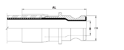
Integral PTFE Lined Cam & Groove Male Fitting |
| Nominal Hose Size |
Outside Diameter D |
*Non-Lined Fitting Length A |
Non-Lined Inside Diameter I |
*PTFE Lined Fitting Length AL |
PTFE Lined Inside Diameter B |
Weight of Fitting |
| in |
mm |
in |
mm |
in |
mm |
in |
mm |
in |
mm |
in |
mm |
Kg |
Lbs |
| 3/4 |
20 |
1.260 |
32.0 |
3.48 |
88.5 |
0.625 |
15.88 |
2.82 |
71.58 |
0.71 |
18.13 |
0.35 |
0.77 |
| 1 |
25 |
1.456 |
37.0 |
3.94 |
100 |
0.80 |
20.24 |
3.74 |
95 |
0.81 |
20.61 |
0.45 |
0.99 |
| 11/4 |
32 |
1.790 |
45.5 |
N/A |
N/A |
N/A |
N/A |
3.62 |
92 |
0.97 |
24.8 |
0.45 |
1.09 |
| 11/2 |
40 |
2.106 |
53.5 |
4.86 |
123.5 |
1.25 |
31.75 |
3.98 |
101 |
1.35 |
34.40 |
0.84 |
1.85 |
| 2 |
50 |
2.480 |
63.0 |
5.47 |
139 |
1.75 |
44.45 |
4.61 |
117 |
1.72 |
43.75 |
1.10 |
2.42 |
| **21/2 |
65 |
2.980 |
75.8 |
4.13 |
105.0 |
2.23 |
56.60 |
6.50 |
165 |
2.17 |
55.0 |
1.17 |
2.57 |
| **3 |
80 |
3.600 |
91.5 |
4.76 |
120.8 |
2.87 |
73.00 |
6.98 |
177.4 |
2.84 |
72.2 |
1.45 |
3.20 |
* Fitting lengths listed are for Bioflex Ultra RC, SI and BK hose grades. Shorter lengths apply for other hose grades
**Non-Lined 21/2" and 3" sizes are only available as Direct Crimp Fittings
PTFE Lined Male Cam & Groove X Flange Adaptors |
  |
| Cam Action Adaptor Size |
Flange Size & Specification |
ØD |
A |
ØI |
Weight of Fitting |
| in |
mm |
in |
mm |
in |
mm |
in |
mm |
kg |
lbs |
| 1 |
25 |
1" ANSI 150 |
2 |
50 |
41/8 |
105 |
0.84 |
21 |
1.246 |
2.75 |
| 1 |
25 |
DN25/PN16 |
2.58 |
64 |
41/8 |
105 |
0.84 |
21 |
1.538 |
3.39 |
| 1 1/2 |
40 |
1 1/2 ANSI 150 |
2.87 |
73 |
43/8 |
118 |
1.35 |
34 |
2.228 |
4.92 |
| 1 1/2 |
40 |
DN40/PN16 |
3.47 |
88 |
43/8 |
118 |
1.35 |
34 |
2.753 |
6.07 |
| 2 |
50 |
2" ANSI 150 |
3.63 |
92 |
43/8 |
118 |
1.69 |
43 |
3.359 |
7.40 |
| 2 |
50 |
DN50/PN16 |
4 |
102 |
43/8 |
118 |
1.69 |
43 |
3.714 |
8.19 |
Note: Other Flange Specifications and Pressure Ratings are also available. Non-Lined adaptors and Female Cam & Groove X Flange Adaptors are also available, to special order.
 |
Sanitary Triclamp Fittings
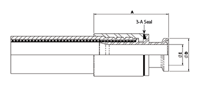
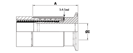
PTFE lined and flared
Introduction
Advantages are - unrestricted clean flow of fluids, no fluid entrapment areas, and all PTFE wetted surfaces internally. Available as standard, stocked fittings in the listed sizes, or in other sizes to special order.
End Fitting Specifications
- ASME BPE
- DIN32676
- BS4825 Pt 3 - equivalent to ASME BPE
- ISO 1127
End Fitting Materials
- Fittings in Grade 316L SS (= BS 316 S11 = EN 1.4404)
- Ferrules, most in Grade 304 SS, some sizes in Grade 316L SS
Temperature and Pressure Ratings
- Pressures up to 16 Bar (230 psi)
- Temperatures upto 120˚C (250˚F) with EPDM Gaskets
- Temperatures up to 180˚C (356˚F) with PTFE, Silicone or Viton Gaskets
- Higher Pressures & Temperatures possible with Special Clamps and appropriate Seals.
Note: The inside lip of the Aflex flared face design is hot formed to a square edge. This prevents a gap for fluid entrapment between the rubber seal and the sealing face. Other suppliers designs have rounded edges, which opens a gap for fluid entrapment.
|
 |
'Beaded' Triclover Fittings
This fitting design is available to special order. No separate seal is required for this design, eliminating any seal compatibility problems.
|
| |
Nominal Hose Size |
Flange Diameter D |
Outlet Diameter I |
Fitting Length A |
3A |
| in |
in |
mm |
in |
mm |
in |
mm |
|
| Mini-Sanitary Triclamp Fittings |
**3/8 |
0.984 |
25.0 |
3/8 |
9.5 |
2.2 |
56 |
√ |
| **1/2 |
0.984 |
25.0 |
3/8 |
9.5 |
2.3 |
60 |
√ |
| Sanitary Triclamp Fittings |
**5/8 (DN15) |
1.340 |
340 |
5/8 |
15.86 |
3.0 |
77 |
√ |
| 3/4 (DN20) |
1.340 |
34.0 |
0.790 |
20.0 |
3.0 |
77 |
√ |
| 3/4 |
1.984 |
50.5 |
3/4 |
19.0 |
2.6 |
65 |
√ |
| 7/8 |
1.984 |
50.5 |
7/8 |
22.2 |
2.6 |
65 |
√ |
| 1 |
1.984 |
50.5 |
1.024 |
26.0 |
2.6 |
65 |
√ |
| 13/8 |
1.984 |
50.5 |
13/8 |
34.9 |
2.8 |
72 |
√ |
| 11/2 |
1.984 |
50.5 |
13/8 |
34.9 |
3.2 |
80 |
√ |
| 17/8 |
2.516 |
64.0 |
17/8 |
47.6 |
3.3 |
84 |
√ |
| 2 |
2.516 |
64.0 |
17/8 |
47.6 |
3.6 |
91 |
√ |
| 21/2 |
3.050 |
77.5 |
23/8 |
60.2 |
5.3 |
135 |
√ |
| 3 |
3.580 |
91.0 |
27/8 |
72.9 |
5.6 |
142 |
√ |
*Fitting Lengths listed are for Bioflex Ultra RC, SI and BK hose grades. Shorter lengths apply for other hose grades.
**3A- For assemblies with nominal hose bore under 0.75", the maximum assembly length is 457mm (18in) and can only be supplied specifically for 3-A Standard 17-and-23- compliant filling and packaging machine applications. For more information see 3A Sanitary Fittings.
Note: The 7/8”, 13/8” and 17/8” hose sizes can only be supplied as assemblies with lined Sanitary Triclover (or I-Line fittings) at BOTH ends, because other types of fittings (Flange, Camlocks etc) are not available for these sizes of hose.
Non-lined Sanitary Triclamp Fittings
Introduction
There are many different specifications, dimensions and surface finishes for triclamp fittngs. Those listed below are the popular fittings, which are stocked as standard fittings by Aflex.
All the alternative fittings can be supplied to special order if the following information can be given;
- Flange diameter D and Outlet diameter I
- Hose size if known, or Aflex can recommend a hose size to suit
- The internal Surface Finish, if it is required to be better than the ASME BPE SF3 surface finish of <0.76μm.Ra = <30μ in Ra non-electropolished.
- Standard (see below) if known.
Standards
- ASME BPE
- DIN 32676 (types A, B and C are available)
- BS 4825 Pt.3 (equivalent to ASME BPE)
- ISO 1127
End Fitting Materials
- Fittings in AISI 316L = EN 1.4404 = BS 316 S11
- Ferrules, most in Grade 304 SS, some sizes in Grade 316L SS
- Fittings for DIN32676 are available in 1.4435 (316L)
- Fittings in 1.4571, Hastelloy, Monel, PVDF and other materials to special order
Temperature and Pressure Ratings
- Pressures up to 16 Bar (230 psi)
- Temperatures up to 120˚C (250˚F) with EPDM Gaskets
- Temperatures up to 180˚C (356˚F) with PTFE, Silicone or Viton Gaskets
- Higher Pressures and Temperatures with Special Clamps and Gaskets.
Internal Surface Finish Specifications
- ASME BPE SF3 (mechanical polish, not electropolished) Surface Finish, Maximum reading:
<0.76μm Ra = <30μ in. Ra
- ASME BPE SF4 (mechanical polish and electropolished) Surface Finish, Maximum reading:
<0.375μm Ra = <15μ in. Ra (SF4 is the highest level of surface finish specified in ASME BPE, and the standard, stocked fittings listed are all to this finish).
- DIN 32676 H4 (mechanical polish, not electropolished) Surface Finish, Average reading:
<0.4μm Ra = <16μ in. Ra. If the standard SF4 finish is not acceptable, H4 must be requested on the enquiry/order.
Note: ASME BPE Triclamp suppliers often quote an ‘Average’ of surface finish reading only, for example ‘average 15 Ra or better’, but this is not in accordance with the stricter ASME BPE requirement that a ‘Maximum’ for individual readings should be complied with.
Mini-Sanitary Triclamp Fittings
Sanitary Triclamp Fittings
| |
Nominal Hose Size |
Flange Diameter D |
Outlet Diameter I |
Fitting Length A |
Specifications |
†3A
Sanitary |
| in |
in |
mm |
in |
mm |
in |
mm |
ASME BPE |
DIN 32676 |
|
| Mini-Sanitary Triclamp Fittings |
1/4 |
0.984 |
25.0 |
0.172 |
4.37 |
2.4 |
61 |
-SF4 |
- |
- |
| 1/4 |
0.984 |
25.0 |
3/8 |
9.53 |
2.4 |
61 |
-SF4 |
Type C |
- |
| 3/8 |
0.984 |
25.0 |
0.305 |
7.75 |
2.6 |
66 |
-SF4 |
- |
- |
| 3/8 |
0.984 |
25.0 |
3/8 |
9.53 |
2.6 |
66 |
-SF4 |
Type C |
- |
| 1/2 |
0.984 |
25.0 |
5/8 |
15.88 |
2.8 |
72 |
-SF4 |
Type C |
- |
| 1/2 |
0.984 |
25.0 |
3/8 |
9.5 |
2.8 |
72 |
-SF4 |
Type C |
- |
| 3/4 |
0.984 |
25.0 |
5/8 |
15.85 |
3.1 |
79 |
-SF4 |
Type C |
√ |
| Sanitary Triclamp Fittings |
3/4 |
1.340 |
34.0 |
5/8 |
15.88 |
3.0 |
77 |
-SF4 |
Type C |
√ |
| 3/4 |
1.340 |
34.0 |
0.630 |
16.0 |
3.0 |
77 |
- |
Type A |
√ |
| 1/2 |
1.984 |
50.5 |
7/8 |
22.2 |
2.8 |
72 |
-SF4 |
Type C |
- |
| 1/2 |
1.984 |
50.5 |
13/8 |
34.8 |
2.8 |
72 |
-SF4 |
Type C |
- |
| 3/4 |
1.984 |
50.5 |
0.713 |
18.1 |
3.0 |
77 |
ISO1127 |
Type B |
√ |
| 3/4 |
1.984 |
50.5 |
7/8 |
22.1 |
3.0 |
77 |
-SF4 |
Type C |
√ |
| 3/4 |
1.984 |
50.5 |
5/8 |
15.88 |
3.0 |
77 |
-SF4 |
Type C |
√ |
| 1 |
1.984 |
50.5 |
7/8 |
22.2 |
3.2 |
82 |
-SF4 |
Type C |
√ |
| 1 |
1.984 |
50.5 |
13/8 |
34.8 |
3.2 |
82 |
-SF4 |
Type C |
√ |
| 11/2 |
1.984 |
50.5 |
13/8 |
34.8 |
3.9 |
98 |
-SF4 |
Type C |
√ |
| 11/2 |
2.516 |
64.0 |
17/8 |
47.6 |
3.9 |
98 |
-SF4 |
Type C |
√ |
| 2 |
2.516 |
64.0 |
17/8 |
47.6 |
4.1 |
103 |
-SF4 |
Type C |
√ |
| **21/2 |
3.05 |
77.5 |
2.37 |
60.2 |
2.80 |
71 |
-SF4 |
Type C |
√ |
| **3 |
3.58 |
91 |
2.87 |
72.9 |
3.17 |
80.4 |
-SF4 |
Type C |
√ |
* Fitting Lengths listed are for Bioflex Ultra RC, SI and BK hose grades. Shorter lengths apply for other hose grades.
**21/2" and 3" sizes are only available as Direct Crimp Fittings
†The 3-A Fittings on this page are DC design only, see 3-A Sanitary Fittings for specifications.
 |
Sanitary Triclamp 90° elbow fittings
End Fitting Specifications
- BS4825 Pt 3
- ASME-BPE-a
- Others to Special Order
End Fitting Materials
- Fittings in Grade AISI 316L = EN 1.4404 = BS 316 S11
- Ferrules, most in Grade 304 SS, some sizes in Grade 316L SS
Surface Finish:
- The internal surface is to ASME BPE-SF-3 (<0.76 μm Ra, not electropolished).
- If a specified finish on a particular surface is required, please state on the enquiry and order.
Outlet Diameters
The outlet diameters as listed are in accordance with BS4825. The ASME specification, however, requires these diameters to be 0.005” (0.125mm) less in each case. An Outlet Diameter tolerance of +0.000 -0.005” has therefore been applied, so that the same fitting satisfies requirements of both specifications.
Temperature and Pressure Ratings
- Pressures up to 16 Bar (230 psi)
- Temperatures up to 120˚C (250˚F) with EPDM Gaskets
- Temperatures up to 180˚C (356˚F) with PTFE, Silicone or Viton Gaskets
- Higher Pressures and Temperatures with Special Clamps and Gaskets.
|
|
| Nominal Hose Size |
*Centre Line to Fitting End A
(Bioflex Ultra RC) |
Centre Line to Face B |
Flange Diameter D |
Outlet Diameter I |
Weight of Fitting |
| in |
mm |
in |
mm |
in |
mm |
in |
mm |
in |
mm |
Kgs |
Lbs |
| 1/2 |
13 |
5.78 |
147 |
1.60 |
41.0 |
0.984 |
25.0 |
3/8 |
9.5 |
0.13 |
0.30 |
| 3/4 |
20 |
6.41 |
163 |
1.60 |
41.0 |
0.984 |
25.0 |
5/8 |
16.0 |
0.20 |
0.45 |
| 1 |
25 |
6.53 |
166 |
200 |
51.0 |
1.984 |
50.5 |
7/8 |
22.2 |
0.35 |
0.77 |
| 11/2 |
40 |
7.99 |
203 |
2.75 |
70.0 |
1.984 |
50.5 |
13/8 |
34.9 |
0.59 |
1.30 |
| 2 |
50 |
9.33 |
237 |
3.50 |
88.9 |
2.16 |
64.0 |
17/8 |
47.6 |
0.93 |
2.05 |
| 21/2 |
65 |
7.32 |
186.0 |
4.25 |
108.0 |
3.05 |
77.5 |
2.37 |
60.2 |
1.48 |
3.25 |
| 3 |
80 |
10.43 |
265.0 |
5.00 |
127.0 |
3.58 |
91.0 |
2.87 |
72.9 |
1.99 |
4.38 |
* Fitting Lengths listed are for Bioflex Ultra RC, SI and BK hose grades. Shorter lengths apply for other hose grades.
**21/2" and 3" sizes are only available as Direct Crimp Fittings
DIN 11851 Fittings
Description
DIN11851 male and female fittings, integral PTFE lined and flared. The PTFE sealing face is hot moulded into the correct shape, designed to achieve the optimum pressure seal. 90˚ elbow PTFE lined fittings are available for some sizes and grades.
Specifications
- Generally to German DIN 11851 specifications.
End Fitting Materials
- Spigots in Grade 316L SS (Non-Lined Spigot in 1.4571)
- Nuts in Grade 304 SS
- Ferrules, most in Grade 304 SS, some sizes in Grade 316L SS
Surface Finish: (Non-Lined Fittings only)
- All surface finishes are to ASME BPE-SF-3>0.76μm Ra, mechanical polish.
- If a specified finish on a particular surface is required, please state on the enquiry and order.
Temperature & Pressure Ratings
- Sizes up to 11/2” MWP = 40 Bar (580 psi) up to 140˚C (284˚F)
- Sizes 2” to 3” MWP = 25 Bar (360 psi) up to 140˚C (284˚F)
Except: where the applicable hose pressure/temperature ratings are lower
Note: The PTFE lined male fitting is designed to be used without a rubber seal. Please note that when connecting to a PTFE Lined DIN 11851 Male, extra spanner tightening of the nut is sometimes required in order to provide a leak free connection.
Non-Lined DIN11851 Fittings
Non-Lined DIN11851 Male Fitting |
Non-Lined DIN11851 Female Fitting |
| Nominal Hose Size = 'I' Dia |
*Male Fitting
Length A
(Bioflex Ultra RC) |
*Female Fitting Length A
(Bioflex Ultra RC) |
Fitting Inside Diameter |
Weight of Fitting Male |
Weight of Fitting Female |
†3A |
| in |
mm |
in |
mm |
in |
mm |
in |
mm |
kg |
lbs |
kg |
lbs |
|
| 1/2 |
15 |
2.95 |
75 |
2.58 |
65 |
0.38 |
9.5 |
0.13 |
0.29 |
0.18 |
0.40 |
- |
| 3/4 |
20 |
3.31 |
84 |
3.00 |
76 |
0.63 |
15.9 |
0.27 |
0.58 |
0.24 |
0.53 |
√ |
| 1 |
25 |
3.58 |
91 |
3.20 |
81 |
0.80 |
20.2 |
0.37 |
0.82 |
0.41 |
0.90 |
√ |
| 11/4 |
32 |
4.02 |
102 |
3.82 |
97 |
1.03 |
26.2 |
0.50 |
1.09 |
0.52 |
1.15 |
√ |
| 11/2 |
40 |
4.14 |
105 |
3.82 |
97 |
1.25 |
31.8 |
0.70 |
1.45 |
0.75 |
1.65 |
√ |
| 2 |
50 |
4.17 |
106 |
3.94 |
100 |
1.75 |
44.5 |
0.84 |
1.85 |
1.11 |
2.45 |
√ |
| **21/2 |
65 |
3.23 |
82 |
3.03 |
77 |
2.25 |
57.2 |
1.27 |
2.79 |
1.59 |
3.50 |
√ |
| **3 |
80 |
3.23 |
82 |
2.97 |
75.5 |
2.63 |
66.7 |
1.62 |
3.56 |
2.04 |
4.49 |
√ |
**Non-LIned 21/2" and 3" sizes are only available as Direct Crimp Fittings
† 3A approved for CIP when used with approved gaskets. The 3-A Fittings in this table are DC design only, see 3-A Sanitary Fittings for specifications.
PTFE Lined DIN11851 Fittings
PTFE Lined DIN11851 Male Fitting |
PTFE Lined DIN11851 Female Fitting |
| Nominal Hose Size = 'I' Dia |
*Male Fitting
Length A
(Bioflex Ultra RC) |
*Female Fitting Length A
(Bioflex Ultra RC) |
Fitting Inside Diameter |
Weight of Fitting Male |
Weight of Fitting Female |
†3A |
| in |
mm |
in |
mm |
in |
mm |
in |
mm |
kg |
lbs |
kg |
lbs |
|
| **1/2 |
15 |
2.28 |
58 |
2.00 |
51 |
0.51 |
13.0 |
0.13 |
0.29 |
0.17 |
0.37 |
√ |
| 3/4 |
20 |
2.44 |
62 |
2.17 |
55 |
0.76 |
19.4 |
0.21 |
0.46 |
0.23 |
0.51 |
√ |
| 1 |
25 |
3.00 |
76 |
2.75 |
70 |
1.01 |
25.7 |
0.30 |
0.66 |
0.40 |
0.88 |
√ |
| 11/4 |
32 |
2.75 |
70 |
2.50 |
64 |
1.28 |
32.4 |
0.37 |
0.82 |
0.51 |
1.12 |
√ |
| 11/2 |
40 |
2.84 |
72 |
3.00 |
76 |
1.53 |
38.9 |
0.42 |
0.93 |
0.73 |
1.60 |
√ |
| 2 |
50 |
3.47 |
88 |
3.55 |
90 |
2.03 |
51.6 |
0.65 |
1.43 |
1.10 |
2.42 |
√ |
| 21/2 |
65 |
5.91 |
150 |
5.20 |
132 |
2.51 |
63.7 |
1.50 |
3.29 |
1.42 |
3.12 |
√ |
| 3 |
80 |
6.38 |
162 |
5.51 |
140 |
3.02 |
76.8 |
1.90 |
4.19 |
1.82 |
4.01 |
√ |
* Fitting Lengths listed are for Bioflex Ultra RC, SI and BK hose grades. Shorter lengths apply for other hose grades.
** 3A - For assemblies with nominal hose bore under 0.75", the maximum assembly length is 457mm (18in) and can only be supplied specifically for 3-A Standard17- and 23- compliant filing and packaging machine applications.
† 3A - Clean out of place (COP) only.
SMS & RJT Female Fittings
End Fitting Specifications
- SMS generally to Swedish SMS1148 specification.
- RJT generally to British BS4825 Pt 5 specification.
End Fitting Materials
- Spigots in Grade 316L SS
- Nuts in Grade 304 SS
- Ferrules, most in Grade 304 SS, some sizes in Grade 316L SS
Surface Finish: (Non-Lined Fittings only)
- All surface finishes are to ASME BPE-SF-O (No finish required).
- If a specified finish on a particular surface is required, please state on the enquiry and order.
Temperature and Pressure Ratings
- Pressures up to 10 Bar (150 psi)
- Temperatures up to 150˚C (302˚F).
90˚ Elbows
- PTFE Lined 90° Elbow Fittings are available for some sizes and grades.
PTFE Lined SMS Female Fitting
| Nominal Hose Size |
*Fitting Length A
(Bioflex Ultra RC) |
Fitting Inside Diameter I |
Weight of Fitting |
†3A |
| in |
mm |
in |
mm |
in |
mm |
kg |
lbs |
|
| 1 |
25 |
3.39 |
86 |
1 |
25.7 |
0.40 |
0.88 |
√ |
| 11/4 |
32 |
3.39 |
86 |
11/4 |
32.4 |
0.51 |
1.12 |
√ |
| 11/2 |
40 |
3.70 |
94 |
11/2 |
38.9 |
0.73 |
1.60 |
√ |
| 2 |
50 |
4.10 |
104 |
2 |
51.6 |
1.10 |
2.42 |
√ |
| 21/2 |
65 |
6.38 |
162 |
21/2 |
63.7 |
1.78 |
3.92 |
√ |
| 3 |
80 |
6.85 |
174 |
3 |
76.8 |
2.15 |
4.73 |
√ |
*Fitting Lengths listed are for Bioflex Ultra RC, SI and BK hose grades. Shorter lengths apply for other hose grades.
† 3A - Clean out of place (COP) only. For more information see 3-A Sanitary Fittings.
RJT Female Fitting, Non-Lined
| Nominal Hose Size |
*Fitting Length A (Bioflex Ultra A) |
Fitting Inside Diameter I |
Weight of Fitting |
| in |
mm |
in |
mm |
in |
mm |
kg |
lbs |
| 1 |
25 |
2.95 |
75 |
0.80 |
20.24 |
0.40 |
0.88 |
| 11/2 |
40 |
3.58 |
91 |
1.25 |
31.75 |
0.73 |
1.60 |
| 2 |
50 |
3.66 |
93 |
1.75 |
44.45 |
1.10 |
2.42 |
*Fitting Lengths listed are for Bioflex Ultra RC, SI and BK hose grades. Shorter lengths apply for other hose grades.
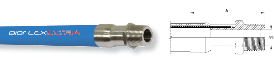
NPT & BSPT fittings
End Fitting Specifications
- NPT Taper Threads to American National Standard Pipe Taper Thread design to ANSI/AMSE B1.20.1.
- BSPT Threads to British Standard Pipe Taper Thread design to BS21
Alternatives - Parallel Threads, Metric Threads and Others.
End Fitting Materials
- Fittings in Grade 316L SS
- Ferrules, most in Grade 304 SS, some sizes in Grade 316L SS
- Available in other materials to special order
Alternatives - Hydraulic design BSPT Male Fittings in Zinc Plated Carbon Steel, to special order.
Surface Finish:
- All surface finishes are to ASME BPE-SF-O (No finish required).
- If a specified finish on a particular surface is required, please state on the enquiry and order.
Fixed Male NPT or BSPT
Nominal
Hose Size
|
NPT or BSPT
Thread Size
|
*Fitting Length A
(Bioflex Ultra RC) |
Fitting Inside
Diameter I
|
Weight of Fitting
|
| in
|
mm
|
in
|
in
|
mm
|
in
|
mm
|
kg
|
lbs
|
| 1/2
|
13
|
1/2
|
3.30 |
84
|
0.38
|
9.53
|
0.10 |
0.22
|
| 3/4
|
20
|
3/4
|
3.74
|
95
|
0.63
|
15.88
|
0.18
|
0.40 |
| 1
|
25
|
1
|
4.13
|
105
|
0.80 |
20.24
|
0.29
|
0.64
|
| 11/4
|
32
|
11/4
|
4.90 |
124
|
1.00 |
25.40 |
0.45
|
0.99
|
| 11/2
|
40
|
11/2
|
5.19
|
132
|
1.25
|
31.75
|
0.60 |
1.32
|
| 2
|
50
|
2
|
5.78
|
142
|
1.75
|
44.45
|
0.84
|
1.85
|
| **21/2 |
65 |
21/2 |
5.31 |
135 |
2.25 |
57.15 |
1.84 |
4.04 |
| **3 |
80 |
3 |
5.39 |
137 |
2.63 |
66.70 |
2.49 |
5.47 |
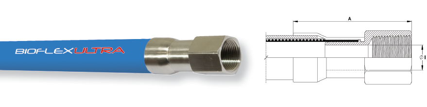
Fixed Female NPT
| Nominal Hose Size |
NPT Thread Size |
*Fitting Length A
(Bioflex Ultra RC) |
Fitting Inside Diameter I |
Weight of Fitting |
| in |
mm |
in |
in |
mm |
in |
mm |
kg |
lbs |
| 1/2 |
13 |
1/2 |
3.42 |
87 |
0.38 |
9.53 |
0.18 |
0.40 |
| 3/4 |
20 |
3/4 |
3.66 |
93 |
0.63 |
15.88 |
0.22 |
0.49 |
| 1 |
25 |
1 |
4.13 |
105 |
0.80 |
20.24 |
0.33 |
0.73 |
| 11/2 |
40 |
11/2 |
4.80 |
122 |
1.25 |
31.75 |
0.75 |
1.65 |
| 2 |
50 |
2 |
4.96 |
126 |
1.75 |
44.45 |
1.06 |
2.34 |
* Fitting Lengths listed are for Bioflex Ultra RC, SI and BK hose grades. Shorter lengths apply for other hose grades.
** 21/2" and 3" sizes are only available as Direct Crimp Fittings
BSP 60° Cone Seat Female Fittings
End Fitting Specifications
- BSPP Threads to British Standard Pipe Parallel Thread design to BS21, 60˚ Cone Seat design, or Flat Seat.
Alternatives :
- Cone Seat Female Union Fittings can be supplied with a BSPP BSPT Taper Male Adaptor if required.
End Fitting Materials
- Spigots in Grade 316L SS
- Nuts in Grade 316L SS
- Ferrules, most in Grade 304 SS, some sizes in Grade 316L SS
Alternatives:
- Hydraulic design Cone Seat Female Unions can be supplied in Zinc Plated Carbon Steel to special order.
- Lug Nuts can be supplied in Gun Metal (Bronze) if required.
Surface Finish:
- All surface finishes are to ASME BPE-SF-O (No finish required).
- If a specified finish on a particular surface is required, please state on the enquiry and order.
BSP 60° Cone Seat Female Union Fitting
| Nominal Hose Size |
NPT or BSPT
Thread Size |
*Fitting Length A
(Bioflex Ultra RC) |
Fitting Inside Diameter I |
Weight of Fitting |
| in |
mm |
in |
in |
mm |
in |
mm |
kg |
lbs |
| 1/2 |
13 |
1/2 |
3.27 |
83 |
0.37 |
9.35 |
0.11 |
0.25 |
| 3/4 |
20 |
3/4 |
3.62 |
92 |
0.63 |
15.88 |
0.15 |
0.34 |
| 1 |
25 |
1 |
3.86 |
98 |
0.80 |
20.24 |
0.24 |
0.53 |
| 11/4 |
32 |
11/4 |
3.98 |
101 |
1.03 |
26.21 |
0.46 |
1.01 |
| 11/2 |
40 |
11/2 |
4.65 |
118 |
1.25 |
31.75 |
0.72 |
1.59 |
| 2 |
50 |
2 |
4.80 |
122 |
1.75 |
44.45 |
0.99 |
2.19 |
| **21/2 |
65 |
21/2 |
3.15 |
80 |
2.25 |
57.15 |
1.37 |
3.02 |
| **3 |
80 |
3 |
3.21 |
81.5 |
2.63 |
66.70 |
2.10 |
4.62 |
BSP Flat Face Lug Nut Female Fitting
| Nominal Hose Size |
BSPP Thread Size |
Fitting Length A
(Bioflex Ultra RC) * |
Fitting Bore Diameter I |
Weight of Fitting |
| in |
mm |
in |
in |
mm |
in |
mm |
kg |
lbs |
| 1 |
25 |
1 |
3.70 |
94 |
0.80 |
20.24 |
0.25 |
0.55 |
| 11/2 |
40 |
1 1/2 |
3.66 |
93 |
1.25 |
31.75 |
0.61 |
1.33 |
| 2 |
50 |
2 |
3.70 |
94 |
1.75 |
44.45 |
0.88 |
1.95 |
* Fitting Lengths listed are for Bioflex Ultra RC, SI and BK hose grades. Shorter lengths apply for other hose grades.
**21/2" and 3" sizes are only available as Direct Crimp Fittings
JIC Fittings
End Fitting Specifications
- SAE J514 37˚ Flare JIC Female Fitting
- 37˚ JIC Male-to-NPT Male/Female Adaptors
- NPT Threads to ANSI/AMSE B1.20.1
Temperature and Pressure Ratings
- Same Maximum Working Pressure and Temperature as for the relevant size of Bioflex Ultra Hose in the Size, Grades, Pressures and Weights table.
Note: Not usable with SAE 45˚ Flare fittings which have the same thread.
End Fitting Materials
- Spigots in Grade 316L SS
- Nuts in 316L SS
- Ferrules, most in Grade 304 SS, some sizes in Grade 316L SS
Alternatives:
- Available in other materials to special order
Surface Finish:
- All surface finishes are to ASME BPE-SF-O (No finish required).
- If a specified finish on a particular surface is required, please state on the enquiry and order.
| Nominal Hose Size |
37 ° JIC
Thread Size |
*Fitting Length A
(Bioflex Ultra RC) |
Hex Size H |
Fitting Inner Diameter I |
Weight of Fitting |
| in |
mm |
in |
in |
mm |
in |
mm |
in |
mm |
kg |
lbs |
| 1/2 |
13 |
3/4 - 16 |
2.76 |
70 |
0.88 |
22.2 |
0.38 |
9.5 |
0.11 |
0.24 |
| 3/4 |
20 |
11/16 - 12 |
3.07 |
78 |
1.25 |
31.7 |
0.63 |
15.9 |
0.15 |
0.34 |
| 1 |
25 |
1 5/16 - 12 |
3.23 |
82 |
1.50 |
38.1 |
0.80 |
20.2 |
0.23 |
0.52 |
| 11/2 |
40 |
1 7/8 - 12 |
4.00 |
102 |
2.25 |
57.1 |
1.25 |
31.7 |
0.72 |
1.58 |
| 2 |
50 |
2 1/2 - 12 |
4.33 |
110 |
2.88 |
73.0 |
1.75 |
44.4 |
0.99 |
2.18 |
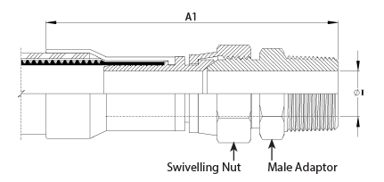
JIC to NPT Male Union
(including a JIC Male to NPT Male Adaptor)
| Nominal Hose Size |
*Male Union Length A1
(Bioflex Ultra RC) |
Weight of Fitting |
| in |
mm |
in |
mm |
kgs |
lbs |
| 1/2 |
13 |
4.13 |
105 |
0.22 |
0.48 |
| 3/4 |
20 |
4.92 |
125 |
0.33 |
0.72 |
| 1 |
25 |
5.43 |
138 |
0.52 |
1.15 |
JIC to NPT Female Union
(including a JIC Male to NPT Female Adaptor)
*Female Union Length A2
(Bioflex Ultra RC) |
Fitting Inner Diameter I |
Weight of Fitting |
| in |
mm |
in |
mm |
kg |
lbs |
| 4.25 |
108 |
0.38 |
9.5 |
0.21 |
0.47 |
| 4.80 |
122 |
0.63 |
15.9 |
0.33 |
0.74 |
| 5.12 |
130 |
0.80 |
20.2 |
0.68 |
1.50 |
*Fitting lengths listed are for Bioflex Ultra RC, SI and BK hose grades. Shorter lengths apply for other hose grades.
PTFE Dip Pipe Fittings
Fixed Dip Pipes
Description
Fixed Dip Pipes are fairly rigid, thick wall PTFE tubes, either straight or 90˚ elbowed, which are directly crimped to the end of Bioflex Ultra hoses. They are designed for insertion into drums, tanks and reaction vessels in order to suction drain (or inject) process fluids transferred through the hose.
Materials
- Standard dip pipes are in anti-static (AS) PTFE
- Ferrules, most in Grade 304 SS, some sizes in Grade 316L SS
How to order
Specify the size and material of the dip pipe, whether it is straight or 90˚ elbowed. Give the length of the straight leg of the dip pipe and the length of the rest of the hose assembly separately.
Maximum Working Pressures
Dip Pipes are normally only tested to 6 Bar Pressure, and are not suitable for use at pressures higher than 3 Bar. They are usable at negative pressure up to -0.9bar vacuum.
If higher pressure ratings are required, consult Aflex Hose.
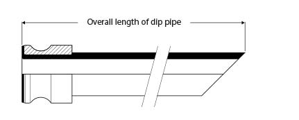
Lengths
Dip Pipes are supplied as standard in 1 metre straight lengths, but can be supplied in any length to individual requirements.
Fixed Dip Pipe (90˚ Elbow) |
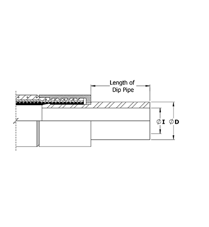
Fixed Dip Pipe (Straight) |
| Nominal Hose Bore Size |
Approximate Dip Pipe Dimentions |
| Outside Diameter D |
Inside Diameter I |
| in |
mm |
in |
mm |
in |
mm |
| 3/4 |
20 |
0.87 |
22 |
0.51 |
13 |
| 1 |
25 |
1.14 |
29 |
0.83 |
21 |
| 11/2 |
40 |
1.54 |
39 |
1.00 |
27 |
| 2 |
50 |
2.17 |
55 |
1.58 |
40 |
Detachable Dip Pipes
Description
As Fixed Dip Pipes above, but connected to the hose through an end fitting, not by crimping direct to the hose.
Design
A straight, or 90˚ elbowed anti-static PTFE Dip Pipe, fitted with a Flange or Cam & Groove Male PTFE Lined & Flared end fitting.
The most usual end fitting is a Cam Male (as shown), so the dip pipe can then be connected to a hose with a Cam Female end fitting.
Specifications
As above for Fixed Dip Pipes
Detachable Dip Pipe
90° Elbow Fittings
PTFE Lined 90° Elbow Fittings
All of the PTFE lined end fittings described on previous pages can be fitted as 90˚ elbow PTFE lined fittings to the design shown, to the sizes listed.
- All grades of hose can be used, except PB.
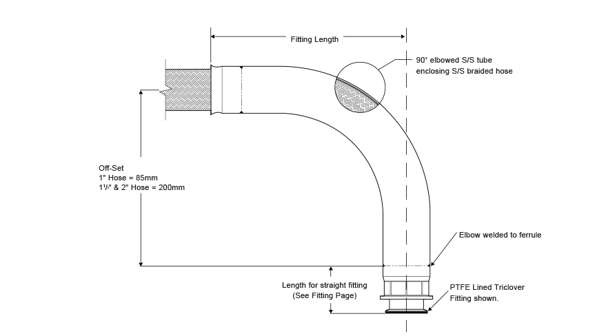
| Hose Bore Size |
Off-Set |
Fitting Length |
Weight Of Fitting |
| |
mm |
mm |
Kg |
Lbs |
| 7/8" or 1" |
85 |
143 |
0.485 |
1.07 |
| 13/8" or 11/2" |
200 |
237 |
1.372 |
3.03 |
| 17/8" or 2" |
200 |
314 |
1.678 |
3.70 |
Non-Lined 90° Elbow Fittings
A 90˚ elbow attached to the hose can be supplied non-PTFE lined, as shown, for any size or grade of hose or type of fittings, to special order.
3-A Sanitary Fittings

3-A Sanitary standards require the hose end fitting to be sealed against the ingress of external fluid into the fitting construction. Aflex Hose have implemented a silicone seal between the ferrule and fi tting to address this requirement. Standard Bioflex Ultra fittings are not available with the 3-A seal feature and therefore a different fitting type is required.
When ordering customers should specify that the hose assembly must meet 3-A sanitary requirements. The 3-A symbol and appropriate marking to 3-A requirements will be applied to the hose assembly.
Note that 3-A hose assemblies have slightly reduced MWP and these are tabulated separately within this section.
Bioflex Ultra Silicone Cover hoses are soakable.
The Aflex Hose 3-A certificate is available to view on our website in the 'certifications' section. The Aflex Hose 3-A certificate is also available to view on the 3-A Sanitary website . Follow the link to the database search page and search for “Aflex Hose” under view company listings.
3-A Maximum Working Pressure - Hose Assembly MWP
| Nominal Hose Size |
*Maximum Working Pressure |
| in |
mm |
psi |
Bar |
| 3/8 |
9.5 |
1000 |
70 |
| 1/2 |
15 |
870 |
60 |
| 5/8 |
16 |
725 |
50 |
| 3/4 |
20 |
650 |
45 |
| 7/8 |
22 |
800 |
55 |
| 1 |
25 |
580 |
40 |
| 11/4 |
32 |
580 |
40 |
| 13/8 |
35 |
580 |
40 |
| 11/2 |
40 |
580 |
40 |
| 17/8 |
48 |
500 |
35 |
| 2 |
50 |
400 |
28 |
| 21/2 |
65 |
290 |
20 |
| 3 |
80 |
218 |
15 |
*The Maximum Working Pressure stated may be reduced as required by the fitting specification.
3-A Sanitary and Mini-Sanitary Triclamp Fitting Specifications
3-A Mini-Sanitary Triclamp Fitting |
3-A Sanitary Triclamp Fitting |
|
Mini-Sanitary
Triclamp
Fittings
|
Nominal Hose Size |
Fitting Length A |
| in |
in |
mm |
| 1/4 |
1.3 |
33 |
| 1/4 |
1.3 |
33 |
| 3/8 |
1.7 |
42 |
| 3/8 |
1.7 |
42 |
| 1/2 |
1.7 |
44 |
| 1/2 |
1.7 |
44 |
| 3/4 |
2.0 |
50 |
Sanitary
Triclamp
Fittings |
3/4 |
2.0 |
50 |
| 3/4 |
2.0 |
50 |
| 1/2 |
1.7 |
44 |
| 1/2 |
1.7 |
44 |
| 3/4 |
1.8 |
45 |
| 3/4 |
1.8 |
45 |
| 3/4 |
1.8 |
45 |
| 1 |
2.3 |
58 |
| 1 |
2.3 |
58 |
| 11/2 |
2.6 |
67 |
| 11/2 |
2.6 |
67 |
| 2 |
3.1 |
78 |
| 21/2 |
2.80 |
71 |
| 3 |
3.17 |
80.4 |
Specifications other than 'Fitting Length A' for 3A Sanitary and Mini-Sanitary Triclamp Fittings can be found in 'Sizes, Grades, Bend Radii & Dimensions' and 'Sizes, Grades, Pressures & Weights'.
3-A Non-Lined Swivel Flange Specifications
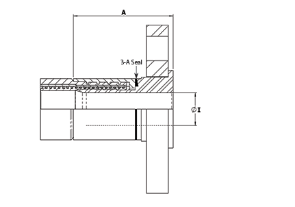
| Nominal Hose Size |
*Fitting Length A
ASA150 |
Flared Diameter D
ASA150 |
Fitting Inside Diameter I
ASA 150 |
Weight of Fitting |
†3A |
| in |
mm |
in |
mm |
in |
mm |
in |
mm |
Kg |
Lbs |
|
| 1/2 |
13 |
1.67 |
42.50 |
1.38 |
35.00 |
0.37 |
9.40 |
0.57 |
1.25 |
- |
| 3/4 |
20 |
1.86 |
47.24 |
1.69 |
42.90 |
0.62 |
15.75 |
0.84 |
1.84 |
√ |
| 1 |
25 |
2.36 |
60.00 |
2.00 |
50.80 |
0.85 |
21.50 |
1.20 |
2.63 |
√ |
| 11/4 |
32 |
2.67 |
67.72 |
2.50 |
63.50 |
1.03 |
26.21 |
1.59 |
3.50 |
√ |
| 11/2 |
40 |
2.75 |
69.86 |
2.87 |
73.00 |
1.25 |
31.75 |
2.15 |
4.73 |
√ |
| 2 |
50 |
3.20 |
81.22 |
3.62 |
92.00 |
1.76 |
44.60 |
2.92 |
6.41 |
√ |
| 21/2 |
65 |
3.70 |
94.00 |
4.13 |
105.00 |
2.25 |
57.15 |
4.36 |
9.59 |
√ |
| 3 |
80 |
3.74 |
95.00 |
5.00 |
127.00 |
2.63 |
66.70 |
6.02 |
13.24 |
√ |
| Nominal Hose Size |
*Fitting Length A
PN10/16 |
Fitting Diameter D
PN10/16 |
Fitting Inside Diameter I
PN10/16 |
Weight of Fitting |
†3A |
| in |
mm |
in |
mm |
in |
mm |
in |
mm |
Kg |
Lbs |
|
| 1/2 |
13 |
1.79 |
45.50 |
1.77 |
45.00 |
0.37 |
9.40 |
0.78 |
1.72 |
- |
| 3/4 |
20 |
2.11 |
53.50 |
2.28 |
58.00 |
0.62 |
15.75 |
1.12 |
2.47 |
√ |
| 1 |
25 |
2.44 |
62.00 |
2.68 |
68.00 |
1.12 |
28.50 |
1.43 |
3.15 |
√ |
| 11/4 |
32 |
2.70 |
68.50 |
3.07 |
78.00 |
1.03 |
26.21 |
2.35 |
5.17 |
√ |
| 11/2 |
40 |
2.91 |
74.00 |
3.49 |
88.00 |
1.70 |
43.10 |
2.76 |
6.06 |
√ |
| 2 |
50 |
3.50 |
89.00 |
4.02 |
102.00 |
2.15 |
54.50 |
3.62 |
7.96 |
√ |
| 21/2 |
65 |
3.62 |
92.00 |
4.80 |
122.00 |
2.25 |
57.15 |
4.58 |
10.07 |
√ |
| 3 |
80 |
3.74 |
95.00 |
5.43 |
138.00 |
2.63 |
66.70 |
6.03 |
13.26 |
√ |
* Fitting lengths listed are for Bioflex Ultra RC, SI and BK hose grades. Shorter lengths apply for other hose grades.
† 3A - Clean out of place (COP) only.
3-A DIN11851 Female Specifications
| Nominal Hose Size |
I Diameter |
Fitting Length A |
Weight of Fitting |
| in |
mm |
in |
mm |
in |
mm |
Kg |
Lbs |
| 1/2 |
15 |
0.37 |
9.4 |
1.63 |
41.5 |
0.20 |
0.44 |
| 3/4 |
20 |
0.62 |
15.8 |
1.87 |
47.5 |
0.34 |
0.76 |
| 1 |
25 |
0.85 |
21.5 |
2.33 |
59.2 |
0.49 |
1.08 |
| 11/4 |
32 |
1.03 |
26.2 |
2.58 |
65.5 |
0.64 |
1.40 |
| 11/2 |
40 |
1.25 |
31.8 |
2.76 |
70.0 |
0.85 |
1.86 |
| 2 |
50 |
1.76 |
44.6 |
3.23 |
82.0 |
1.20 |
2.04 |
| 21/2 |
65 |
2.25 |
57.2 |
3.03 |
77.0 |
1.59 |
3.50 |
| 3 |
80 |
2.63 |
66.7 |
2.97 |
75.5 |
2.04 |
4.49 |
† 3A approved for CIP when used with approved gaskets
|