Hyperline FX |
||||||||||||||||||||||||||||||||||||||||||||||||||||||||||||||||||||||||||||||||||||||||||||||||||||||||||||||||||||||||||||||||||||||||||||||||||||||||||||||||||||||||||||||||||||||||||||||||||||||||||||||||||||||||||||||||||||||||||||||||||||||||||||||||||||||||||||||||||||||||||||||||||||||
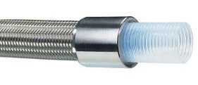
PTFE LINED SMOOTH BORE FLEXIBLE HOSEPTFE, or Polytetrafluoroethylene, comprises long-chain molecules of carbon atoms, each linked to two fluorine atoms. The fluorine atoms provide a helical spiral which surrounds the carbon chain and protects it. It is this structure which creates the unique properties for which PTFE is well-known. Excellent Chemical ResistancePTFE is renowned as the most chemically resistant material known. Only a very few, very unusual substances and conditions can affect it, like Fluorine gas at high temperature and pressure and liquid, boiling sodium metal. PTFE lined hoses can therefore be used for a wider variety of chemicals than any other hose type, making it the ideal choice for very corrosive chemical applications and multi-product applications. Non-Stick SurfaceThe use of PTFE as a surface for cookware products has demonstrated to the world how easily cleanable PTFE surfaces are. This means that PTFE lined hoses can be purged 100% clean more quickly, easily and reliably than any other type of hose. Excellent Temperature RangeThe cookware application also demonstrates another of PTFE’s many attributes - temperature resistance. PTFE itself can be used as a hose liner at temperatures from -150°C up to +260°C, dependent upon the hose design and the application conditions. This is the widest temperature range of any rubber or plastic hose lining material. Hose DesignThe only issue with PTFE as a hose lining material is the best way it can be integrated in to the hose design. This is where Aflex Hose have a proven record of success over the last 30 years. There is a fundamental problem with larger sizes of standard, smooth bore PTFE hose products - as the hose size increases above 1/4”, so smooth bore PTFE lined hose become significantly less flexible, and more easily kinked. One solution is to use a conventional convoluted PTFE lined hose, but the internal convolutions make the hose difficult to assemble, and reduces fluid flow rates due to turbulent flow. Hyperline FX is a new and revolutionary solution to all these problems, providing a unique and patented hose liner design which is flexible in the larger bore sizes, yet which retains a smooth bore. The advantage of a smooth bore as compared with a convoluted bore is that it is easy clean, and does not create “turbulent flow”, which drastically reduces fluid flow rates.
Antistatic PTFE Linings (AS Grade)When electrically resistive fluids like solvents and fuels, or multiphase mixtures are passed through natural PTFE hose at high flow rates, a static charge build up occurs on the inner wall of the PTFE liner, which eventually discharges to the nearest earth creating a leak path through the liner. Antistatic PTFE includes a small quantity of a special carbon black which ensures safe static charge dissipation, in accordance with International Standards. Stainless Steel Wire Braid (SS Grades)The braid protects the PTFE liner tube against internal pressure and mechanical abuse. Aramid Fibre Braid (AM Grades)The aramid fibre is “Tecnora”, a higher specification fibre than Kevlar, with excellent temperature, tensile and abrasion resistant properties. For applications requiring minimum weight for maximum pressure reinforcement.
SPECIFICATIONS FOR HYPERLINE FX HOSE GRADES
*Hydraulic Bore Size - The actual bore sizes of Hyperline FX hose are slightly larger than the nominal size, to allow the insertion and assembly of standard Hydraulic Fittings, using ferrules supplied by Aflex Hose PROPERTIESTemperatures and Pressures Hyperline FX, SS Grades - The MWP listed above should be reduced by 1% for each 1°C above 160°C (1% for each 1.8°F above 320°F) up to a maximum of 260°C (500°F). Hyperline FX, AM Grades - The MWP listed above should be reduced by 1% for each 1°C above 130°C (1% for each 1.8°F above 266°F) up to a maximum of 180°C (356°F). Maximum Working Pressures (MWP) listed are calculated on the basis of a 3:1 safety factor relative to the burst pressure, so Burst Pressure = 3 x MWP. If MWP is required based on a 4:1 safety factor, multiply the listed value by 0.75. Vacuum ResistanceHyperline FX, SS Grades are fully vacuum resistant up to 130°C (266°F). Excellent Flow RatesCompared with conventional convoluted hose designs, Hyperline FX has excellent flow rates due to the smooth bore, which prevents the turbulent fluid flow which occurs in convoluted hose products. Reduced Diffusion RatesHyperline FX is much more resistant to diffusion of liquids or gases than other PTFE hose products, due to its highly compressed, nonporous PTFE matrix. Hyperline FX has been successfully tested to SAE J1737 for resistance to automotive fuel diffusion. Non-Stick Internal SurfaceHyperline FX hose has a smooth bore, non-stick liner which is effectively "self-cleaning", and which resists material build-up inside the hose which may cause bore constriction. ALTERNATIVE DESIGN OPTIONS - HOSE COVERSFor certain applications, it is an advantage to have a flexible plastic or rubber outer cover extruded on to the hose. The cover provides protection for the braid, as well as being easy to clean, and can be printed with a continuous text line. Covered hose is, however, only available to special order, so price and availability are very dependent upon quantities required. Options are:
Other rubbers may also be available. APPLICATIONS FOR HYPERLINE HOSEAutomotive and Motorsport : replacing conventional PTFE hoses in ESP systems, fuel systems, braking systems and oil lines. Refrigeration : refrigerant feed lines to freezer plates, where the high resistance to permeation, together with the flexibility and chemical resistance, are primary advantages. Steam and Gas Lines : where the smooth bore ensures non-turbulent gas flow, leading to noise free operation at higher flow rates, and longer service life. Industrial applications in general where the ease of assembly to end fittings together with the higher flow rates, chemical and temperature resistance and resistance to permeation make Hyperline FX the optimum choice. SUPPLY OPTIONSHyperline FX hose can either be supplied as made up and crimped hose assemblies, or as loose hose for customers to assemble themselves, using ferrules supplied by Aflex Hose, and standard hydraulic end fittings, which can also be supplied by Aflex Hose if required. Easier Assembly : Hyperline FX is very flexible, and is designed to replace conventional flexible tape wrapped convoluted or autoconvoluted PTFE hoses in application where faster, cleaner fluid flow or ease of assembly is paramount. SS or MS ferrules and crimp diameters can be supplied to suit any conventional hydraulic hose tail end fittings. Problems associated with assembling fittings to convoluted hoses, such as leakages, the need for special or sleeved spigots, the need to de-convolute etc. disappear - Hyperline FX is literally as easy to assemble as any smooth bore hose.
Pressure Testing Instructions:All self-assembled hose assemblies must be pressure tested to 1.5 x MWP before end use. HYPERLINE FX HOSE - CUT LENGTHS WITH NON-FLARED ENDSAflex Hose are also able to supply Hyperline Hose in ready-to-assemble pre-cut lengths, with the braid wire at the ends annealed and cut so the cut ends do not flare out. This makes it easier to slide ferrules on to the hose ends during assembly. This can be applied to all sizes of Hyperline FX hoses for minimum quantities of 500+ lengths. Minimum cut length 60mm (2 3/8"), lengths cut to an accuracy of + or - 1.5mm (1/16"). HYPERLINE FX HOSE: SPECIAL USAGE CONDITIONSPTFE Hose - Use with Alkali Metals, Halogens and Halogen containing ChemicalsPTFE hose liners react chemically with Fluorine, Chlorine Trifluoride and molten Alkali Metals. When PTFE lined hose is used to carry Chlorine or Bromine, either as gasses or fluids, they will diffuse into and through the PTFE liner wall thickness. Trace quantities will then combine with atmospheric moisture to corrode any braid/rubber outer coverings. Heavily halogenated chemicals, like Hydrogen Fluoride, Hydrogen Chloride, Phosgene (Carbonyl Chloride) Carbon Tetrachloride and other organic chemicals with a high halogen content can also be absorbed and transmitted through the PTFE liner tube. Other “Penetrating” Fluids and GasesSulphur Trioxide, Methyl Methacrylate, Caprolactam and Glacial Acetic Acid are some other chemicals which can be absorbed and transmitted through the PTFE liner tube wall. Generally, however, as a hydrophobic (non-wetting) material, PTFE is very resistant to the absorption of chemicals. In some cases, PTFE has superior resistance to diffusion, for example to the diffusion of automotive fuels, in comparison with all other plastics and rubbers. Gas/Fluid CyclingThere are some applications where the fluid passing through the hose turns into a gas, then back into a fluid, then into a gas etc, in a cyclic sequence. This is normally associated with changes in temperature and/or pressure. For complex reasons these conditions are extremely damaging to the hose liner, whatever material it is made from. For example, hoses are sometimes used to pass steam, water, steam etc into rubber molding presses, in order to heat the mould, then rapidly cool it before reheating in the next cycle. Hoses of all types fail rapidly in such an application and PTFE lined hoses are no exception. Please contact Aflex Hose for further information if these conditions apply. Connecting Assemblies for Use in ApplicationsThe lengths of hose assemblies and their configuration in use when connected into the application must always be in accordance with the Hose Configuration information at the end of this product literature. When being connected for use in applications, the end fittings on hose assemblies must be connected to correct mating parts in the correct way, using the correct tools, spanners, clamps, nuts and bolts etc. The connections must be sufficiently tightened to ensure that the joint is leak free but not be over tightened as this can damage the sealing surfaces. In applications involving the transfer through the hose of expensive or dangerous fluids or gases, the hoses and connections must be pressure tested in situ before being put in to service. This should be done with some harmless media to 1 1/2 times the maximum working pressure of the hose assembly, as stated in the product literature. If in doubt please contact Aflex Hose for advice. Special ApplicationsAflex Hose PTFE lined hose products are not rated as suitable for use in the following, special applications: All Radioactive Applications involving high energy radiation, including Gamma radiation (degrades PTFE) All Medical Implantation Applications. All Aerospace Applications. Hyperline FX and Quality Assurance, Certification and Approvals
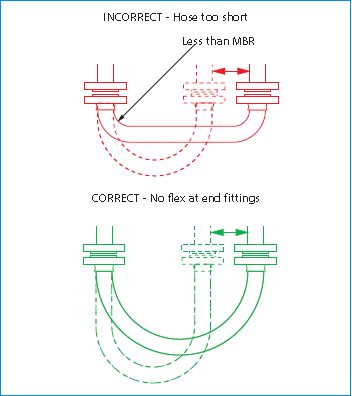
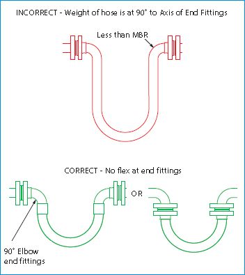
BS EN ISO 9001:2008Aflex products are all manufactured in accordance with BS EN ISO 9001: 2008 Quality Management Systems independently assessed and registered by National Quality Assurance Limited (NQA). TS16949Aflex Hose Ltd manufactures PTFE flexible hose for the automotive industry in accordance with TS16949:2009 and is assessed and certified by National Quality Assurance Limited (NQA). 3-A Sanitary StandardsThe PTFE used in the liner is manufactured solely from materials which meet the requirements of the 3-A Sanitary Standards. Automotive Fuel Hose - SAE J1737Tested and approved for automotive fuel hose use in accordance with SAE J1737. CE Marking (Europe only)Aflex has been assessed by Zurich Engineering and found to comply with the Pressure Equipment Directive 97/23/EC (European Community) Conformity Assessment Module D1, approved to CE Mark applicable hose products, accompanied by a Hose Usage Data Sheet, and a Declaration of Conformity. Attestations of Conformity to ATEX Directive 94/9/EC (Potentially Explosive Atmospheres)Available for hose and assemblies for components used in Gas Zones 1 & 2 and Dust Zones 21 & 22, when applicable. Material Certification to EN10204Available for all the hose or hose assembly components. Certificates of Conformity to BS EN ISO/IEC 17050Are available for all products. Hose Configuration RequirementsHose Assemblies are usually connected at both ends in service. They may then either remain in a fixed, or static configuration or in a flexing, or dynamic configuration. Whether static or dynamic, the First Rule concerning the configuration of the hose is that the bend radius of the hose must never be less than the Minimum Bend Radius (MBR) for the hose as listed in the relevant hose brochure. The most common situation when this is likely to occur is when the hose is flexed at the end fitting, with stress being applied to the hose at an angle to the axis of the end fitting. Typically, this happens either because the length of the hose is too short, or because the weight of the hose plus contents creates a stress at an angle to the end fitting. The Second Rule, therefore, if possible, is to design the configuration to ensure that any flexing in the hose takes place away from the end fittings.
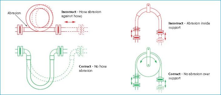
The Third Rule is that the hose configuration should always be designed, and supported where necessary, to avoid any possibility of external abrasion. In some cases, the length, configuration and angle of the hose can be designed to avoid abrasion. In others, static or moving support frames or support wheels are required.
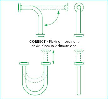
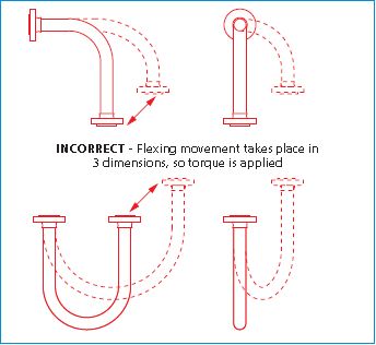
The Fourth Rule is that the hose must not be subjected to torque, either during connection, or as a result of the flexing cycle. Torque (twist) in the hose can be applied during connection if the hose is accidentally twisted, or if the second end being connected is a screwed connection, and the hose is subjected to torque during final tightening. In a flexing application, if any flexing cycle of the hose occurs in 3 dimensions instead of 2, then torque will also occur:
Both Pharmaline and Pharmalex hose have good resistance to a small level of torque, much better resistance that rubber or SS hose types, but it is still the best practice to take whatever steps are necessary to eliminate torque. If in doubt, consult Aflex Hose. HOSE CONFIGURATION & LENGTH CALCULATIONS for LENGTH CALCULATIONS
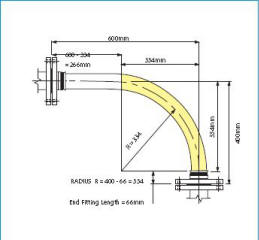
Selecting the hose lengthHyperline FX hose assemblies are made up to the specific lengths required. The hose length is taken from the sealing face at one end of the hose to the same at the other end. The length tolerance is normally +5%-0%. Closer tolerances are available to special order. CALCULATING THE HOSE LENGTHThe formula for calculating the bent section of the hose length around a radius is derived from the basic formula that the circumference of a circle = 2ΠR, where R = the radius of the circle, and Π = a constant, = 3.142. So, if the hose goes around a 90° bend, which is 1/4 of a full circumference, and the radius of the bend is R, then the length of the hose around the bend is = 1/4 x 2ΠR. Or half way round, in a U-shape, = 1/2 x 2ΠR. Note:In calculating the length of a hose assembly, the (non-flexible) length of the end fittings must be added in, also the length of any straight sections of hose, as in the following example: Example:To calculate the length for a 2” bore size hose with flange end fittings, to be fitted in a 90° configuration with one leg 400mm long, the other 600mm long. Length of Bent Section (yellow)= 1/4 x 2ΠR (334) = 1/4 x 2 x 3.142 x 334 = 525mm Length of top, Straight Section, including the top end fitting length 1L = /2 x 2ΠR = 600 - 334 = 266mm Length of bottom end fitting = 66mm Total length of Hose Assembly = 525 + 266 + 66 = 857mm Things to consider
Questions? Contact Carolina Components Group today! |
||||||||||||||||||||||||||||||||||||||||||||||||||||||||||||||||||||||||||||||||||||||||||||||||||||||||||||||||||||||||||||||||||||||||||||||||||||||||||||||||||||||||||||||||||||||||||||||||||||||||||||||||||||||||||||||||||||||||||||||||||||||||||||||||||||||||||||||||||||||||||||||||||||||

Our Commitment to Quality
Above all else, Carolina Components Group is committed to producing components of the highest quality.
Our customers can be assured that the products that they receive meet their stringent quality standards.
Carolina Components Group is a Member or Affiliate of: